


3.0 ATA interface
This drive uses the industry-standard ATA task file interface. It supports
both 8-bit and 16-bit data transfers. It supports ATA programmed in-
put/output (PIO) modes 0, 1, 2, 3 and 4; ATA single-word DMA modes
0, 1 and 2; and ATA multiword DMA modes 0, 1 and 2. The drive also
supports the use of the IORDY signal to provide reliable high-speed data
transfers.
You can use a daisy-chain cable to connect two drives to a single AT
host bus. For detailed information regarding the ATA interface, refer to
the
Draft ATA-3 document X3T10 2008, Revision 6,
subsequently re-
ferred to as the
Draft Proposed ATA-3 Standard
.
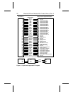
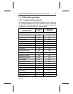
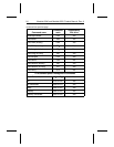
3.1 ATA interface signals and connector pins
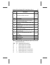
Figure 4 on page 22 summarizes the signals on the ATA interface
connector that the drive supports. For a detailed description of these
signals, refer to the
Draft Proposed ATA-3 Standard.
3.1.1 AT bus signal levels
Signals that the drive receives must have the following characteristics at
the drive connector:
Logic low 0.0V to 0.7V
Logic high 2.0V to 5.25V
Medalist 3240 and Medalist 2531 Product Manual, Rev. A 21