


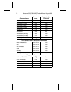

Jumper
for pins
A and B
Jumper
for pins
C and D Configuration
Removed Removed Drive is master; slave drive may be detected
using DASP– signal. CSEL is ignored.
Removed Installed Drive is master; slave drive is present. CSEL
is ignored. DASP– is ignored.
Installed Removed Drive is slave (a master drive should be
present also). CSEL is ignored.
Installed Installed Differentiate master and slave drives using cable
select: If a drive is attached to a connector in which
pin 28 is grounded, then it becomes a master. If a
drive is attached to a connector in which pin 28 is
ungrounded, then it becomes a slave.
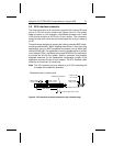
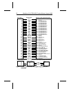
2.3 Remote LED configuration
The drive indicates activity to the host through the DASP– line (pin 39) on
the ATA interface. This line may be connected to a drive status indicator
driving an LED at 5V. The line has a 30 mA nominal current limit. To avoid
potential damage to the drive, the host should include a resistor in line with
the LED for current limiting. This resistor should have a minimum resistance
of 470 ohms (1,000 to 3,000 ohms is recommended).
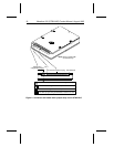
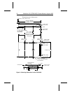
2.4 Drive mounting
You can mount the drive in any orientation. Allow a minimum clearance
of 0.030 inches (0.76 mm) around the entire perimeter of the drive for
cooling. The drive conforms to the industry-standard MCC direct-mount-
ing specifications and requires MCC-compatible connectors for direct-
mounting applications. See Figure 3 on page 18 for drive mounting
dimensions.
Note. The I/O connector pins may extend up to 0.010 inches beyond
the edge of the head/disc assembly.
Caution. To avoid damaging the drive:
• Use M3X0.5
metric
mounting screws
only
.
• Do not insert mounting screws more than 0.150 inches (3.81 mm) into
the mounting holes.
• Do
not
overtighten the screws (maximum torque: 3 inch-lb).
Marathon 810 (ST9816AG) Product Manual, August 1995 17