


3.0 ATA interface
The ST9816AG uses the industry-standard ATA interface. It supports
both 8-bit and 16-bit data transfers. It supports ATA programmed in-
put/output (PIO) modes 0, 1, 2, 3 and 4, ATA single-word DMA modes
0, 1 and 2, and ATA multiword DMA modes 0, 1 and 2. The drive also
supports the use of the IORDY signal to provide reliable high-speed data
transfers.
The drive can differentiate between a hard reset and a soft reset while
in Sleep mode. You can use a daisy-chain cable to connect two drives
to a single AT host bus. For detailed information regarding the ATA
interface, refer to the
Proposed Working Draft of the ATA-2 Draft Pro-
posed American National Standard
, document X3T9.2/948D (sub-
sequently referred to as the Draft Proposed ATA-2 Standard).
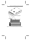
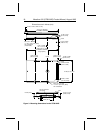
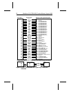
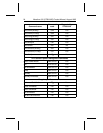
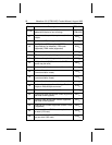
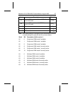
3.1 ATA interface signals and connector pins
Figure 5 on page 22 summarizes the signals on the ATA interface
connector that are supported by the ST9816AG. For a detailed descrip-
tion of these signals, refer to the
Draft Proposed ATA-2 Standard.
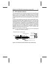
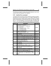
3.1.1 AT bus signal levels
Signals that the drive sends have the following output characteristics at
the drive connector:
Logic Low 0.0V to 0.4V
Logic High 2.5V to 5.25V
Signals that the drive receives must have the following input charac-
teristics, measured at the drive connector:
Logic Low 0.0V to 0.8V
Logic High 2.0V to 5.25V
Marathon 810 (ST9816AG) Product Manual, August 1995 21