2.5 ATA interface connector
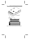
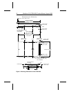
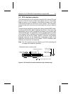
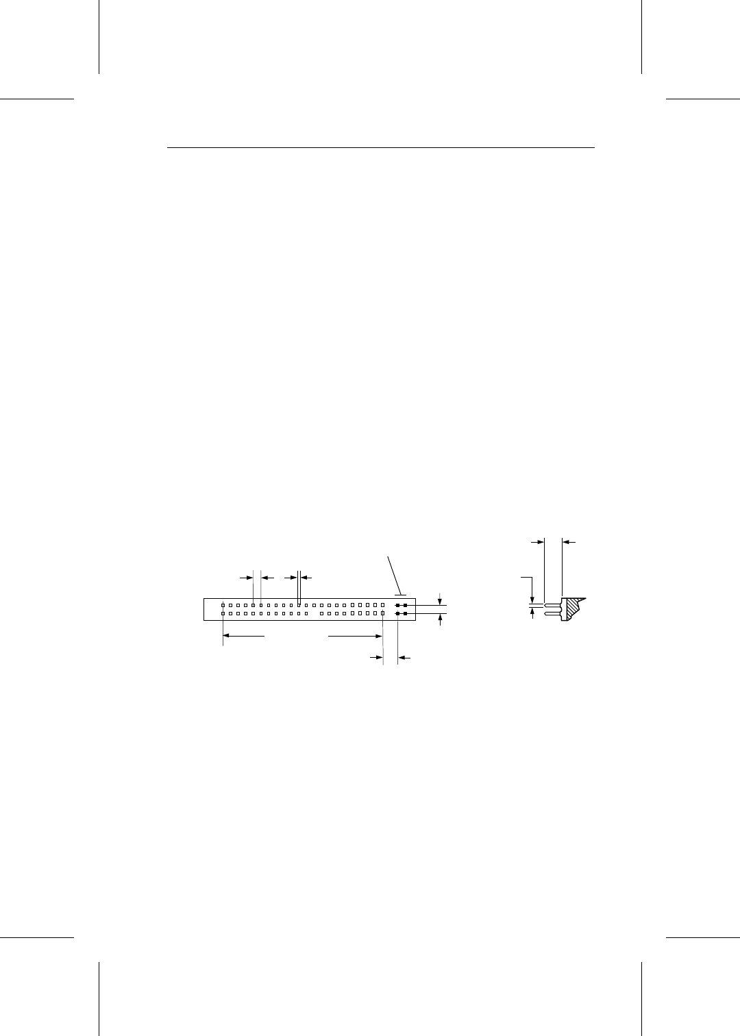
The drive connector is a 44-conductor connector with 2 rows of 22 male
pins on 0.079-inch (2-mm) centers (see Figures 4 and 5). The mating
cable connector is a 44-conductor, nonshielded connector with 2 rows
of 22 female contacts on 0.079-inch (2-mm) centers. The connectors
should provide strain relief and should be keyed with a plug in place of
pin 20.
These drives are designed to support the industry-standard MCC direct-
mounting specifications. When installing these drives in fixed mounting
applications, use only MCC-compatible connectors such as Molex part
number 87368-442
x
. For applications involving flexible cables or printed
circuit cables (PCCs), use Molex part number 87259-4413 or equivalent
to connect the drive to the system. Select a connector that provides
adequate clearance for the master/slave configuration jumpers if the
application requires the use of such jumpers. The ATA interface cable
should be no more than 18 inches long.
Note. The I/O connector pins may extend up to 0.010 inches beyond
the edge of the head/disc assembly.
1.654 (42.01)
0.020 ± 0.002
(0.51 ± 0.05)
0.079 ± 0.003
(2.00 ± 0.08)
0.152 ± 0.005
(3.71
± 0.20)
0.079 ± 0.003 (
2.00 ± 0.08)
0.020 ± 0.002
(0.51 ± 0.05)
Dimensions are in inches (mm)
0.158 ± 0.003 (4.00 ± 0.08)
Master/slave jumpers
Figure 4. ATA Interface connector dimensions (for reference only)
Marathon 810 (ST9816AG) Product Manual, August 1995 19


