


Medalist 17242, 13032, 10232, 8422 and 4312, Rev. A 19
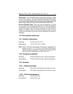
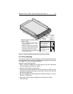
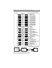
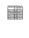
Figure 2. Alternate capacity jumper and master/slave jumper
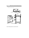
2.4 Drive mounting
You can mount the drive in any orientation using four screws in the side-
mounting holes or four screws in the bottom-mounting holes. See Figure
3 on page 20 for drive mounting dimensions.
Important mounting precautions:
•
Allow a minimum clearance of 0.030 inches (0.76 mm) around the
entire perimeter of the drive for cooling.
•
Use only 6-32 UNC mounting screws.
•
The screws should be inserted no more than 0.22 inch (5.58 mm) into
the bottom mounting holes and no more than 0.20 inch (5.0 mm) into
the side mounting holes.
•
Do not overtighten the mounting screws (maximum torque: 3 inch-lb,
0.34 N.m, 3.45 kgf.cm).
•
Do not use a drive interface cable that is more than 18 inches
(457 mm) long.
pin 1
ATA interface
connector
Alternate capacity and master/slave
jumper settings
3. Use this jumper setting
only
if the drive does
not work with a jumper on pins 7 and 8.
The drive is shipped with a jumper on pins 7
and 8. This configures the drive for master or
single drive operation.
1.
2. Consult your computer manual to determine
whether your computer supports cable select.
135
24
6
7
8
Limit capacity to 2.1 Gbytes
(4,092 cylinders)
4
Slave
Master or single drive
1
Master with non-ATA
compatible slave
3
Enable cable select
2
4-pin power
connector
4. Use this jumper setting if your computer fails
to boot because it cannot recognize drives with
more than 4,092 cylinders.