


PULSAR.2 SAS PRODUCT MANUAL, REV. C 37
9.0 DEFECT AND ERROR MANAGEMENT
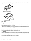
Seagate continues to use innovative technologies to manage defects and errors. These technologies are designed to increase data
integrity, perform drive self-maintenance, and validate proper drive operation.
SCSI defect and error management involves drive internal defect/error management and SAS system error considerations (errors in
communications between the initiator and the drive). In addition, Seagate provides the following technologies used to increase data
integrity and drive reliability:
• Background Media Scan (see Section 9.4)
• Auto-Reallocation (see Section 9.5)
The read error rates and specified storage capacities are not dependent on host (initiator) defect management routines.
9.1 DRIVE INTERNAL DEFECTS/ERRORS
During the initial drive manufacturing test operation at the factory, media defects are identified, tagged as being unusable, and their
locations recorded on the drive primary defects list (referred to as the “P’ list). At factory format time, these known defects are also
deallocated, that is, marked as retired and the location listed in the defects reallocation table. The “P” list is not altered after factory
formatting. Locations of defects found and reallocated during error recovery procedures after drive shipment are listed in the “G” list
(defects growth list). The “P” and “G” lists may be referenced by the initiator using the READ DEFECT DATA command.
Details of the SCSI commands supported by the drive are described in the SAS Interface Manual. Also, more information on the drive Error
Recovery philosophy is presented in the SAS Interface Manual.
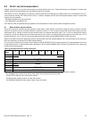
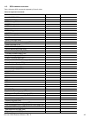
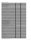
The drive uses a vendor unique format to report defects via the READ DEFECT DATA command pending T10 standardization of a format
for Solid State Devices. This format defect type is defined as 110b in the SCSI FORMAT UNIT command. The definition of the 110b format
is defined in the following table.
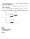
Table 13 SSD Physical format address descriptor
Bit
Byte
7 6 5 4 3 2 1 0
0 (MSB) MEDIA ID
1 (LSB)
2 CHANNEL
3 DIE
4 (MSB) BLOCK
5 (LSB)
6 RESERVED
7 VENDOR UNIQUE
The MEDIA ID field contains an identifier for the flash controller for devices that utilize more than one flash controller.
The CHANNEL field contains the channel number within the corresponding Flash Controller.
The DIE field contains the die number within channel.
The BLOCK field contains the block number within the die.
The VENDOR UNIQUE field may contain vendor unique information.