


SEAGATE 600 PRO SSD PRODUCT MANUAL, REV. A 20
3.4 DRIVE MOUNTING
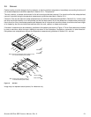
You can mount the drive in any orientation using four screws in the side-mounting holes or four screws in the bottom-
mounting holes. Follow these important mounting precautions when mounting the drive:
• Allow a minimum clearance of 0.030 in (0.76 mm) around the entire perimeter of the drive for cooling as a guideline.
Please refer to Section 3.5 for final cooling requirements.
• Use only M3 x 0.5 metric mounting screws.
• Four (4) threads (0.080 in) minimum screw engagement recommended. Also ensure maximum screw length does not bot-
tom out in mounting holes.
• Do not overtighten the mounting screws (maximum torque: 4.5 in-lb, ± 0.45 in-lb).
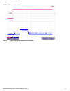
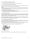
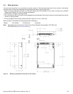
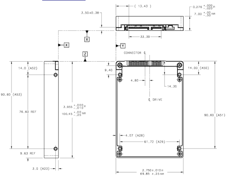
Refer to Figure 3 for detailed mounting configuration dimensions.
Note. These dimensions conform to the Small Form Factor Standard documented in SFF-8201 and
SFF-8223 found at www.sffcommittee.org.
Figure 3. Mounting configuration dimensions (7mm models)
Weight: 7mm models 0.220 pounds 100 grams