


Cheetah 4LP Installation Guide, Rev. B 37
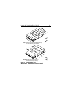
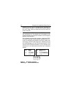
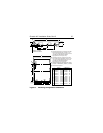
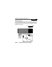
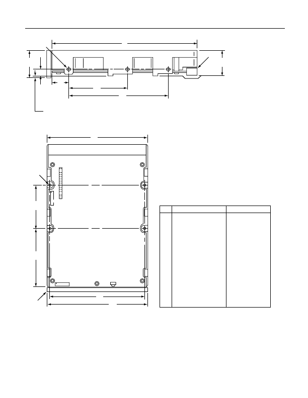
Figure 6. Mounting configuration dimensions
A
F
.050 in. (1.27mm)
minimum clearance
L
D
G
E
C
[3]
[1]
B
H
M
K
J
J2
[4]
[2]
J6 LED
Mounting holes three on each side, 6-32 UNC.
Max screw length into side of drive 0.15 in.
(3.81 mm). Screw tightening torque 6.0 in-lb
(.675 NM) max with minimum thread
engagement of 0.12 in. (3.05 mm).
Mounting holes four on bottom, 6-32 UNC.
Max screw length into bottom of drive 0.15 in.
(3.81 mm). Screw tightening torque 6.0 in-lb
(.675 NM) max with minimum thread
engagement of 0.12 in. (3.05 mm).
Power and interface connectors can extend
past the “A” dimension by 0.040 in (1.02mm).
Decorative front panel.
Notes:
[1]
[2]
[3]
[4]
Inches Millimeters
5.750
4.000
1.000
0.625
4.000
0.250
2.375
3.750
2.370
1.750
1.100
4.100
146.05
101.60
25.40
15.87
101.60
6.35
60.32
95.25
60.20
44.45
27.94
104.14
A
B
C
D
E
F
G
H
J
K
L
M
0.010
0.010
0.026
0.010
0.020
0.005
0.005
0.010
0.010
0.010
0.020
0.010
0.010
±
±
±
±
±
±
±
±
±
±
±
±
.25
.25
.38
.50
.13
.13
.25
.25
.25
.50
.25
.25
±
±
+
–
±
±
±
±
±
±
±
±
±