


Barracuda Serial ATA V Product Manual, Rev. B 23
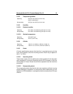
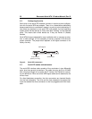
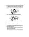
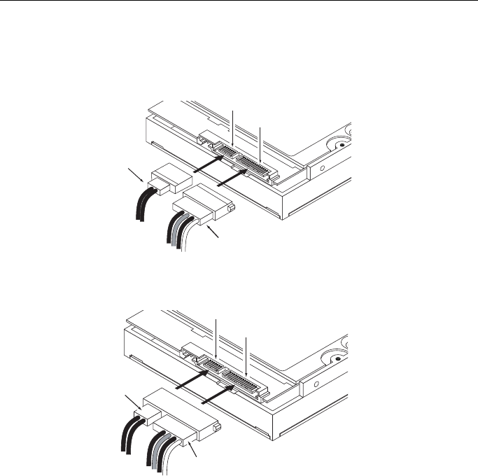
For installations which require cables, you can connect the drive using
cabling which separates the power connector and the SATA signal connector
as illustrated in Figure 5, or you can connect the drive using cabling which
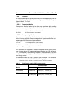
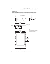
integrates both cables in one molded connector as illustrated in Figure 6.
Figure 5. SATA cabling with separate power and signal attachments
Figure 6. SATA cabling with combined power and signal attachment
Each cable is keyed to ensure correct orientation.
3.4 Drive mounting
You can mount the drive in any orientation using four screws in the side-
mounting holes or four screws in the bottom-mounting holes. See Figure 7 on
page 24 for drive mounting dimensions. Follow these important mounting
precautions when mounting the drive:
• Allow a minimum clearance of 0.030 inches (0.76 mm) around the entire
perimeter of the drive for cooling.
• Use only 6-32 UNC mounting screws.
• The screws should be inserted no more than 0.200 inch (5.08 mm) into the
bottom mounting holes and no more than 0.14 inch (3.55 mm) into the side
Power cable
Signal cable
Signal connector
Power connector
Signal connector
Power connector
Signal cable
Power cable