


SEAGATE ENTERPRISE CAPACITY 3.5 HDD V4 SAS PRODUCT MANUAL, REV. A 44
10.0 INSTALLATION
Enterprise Capacity 3.5 HDD v4 disk drive installation is a plug-and-play process. There are no jumpers, switches, or terminators on the
drive.
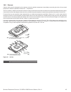
SAS drives are designed to be used in a host system that provides a SAS-compatible backplane with bays designed to accommodate the
drive. In such systems, the host system typically provides a carrier or tray into which users need to mount the drive. Mount the drive to the
carrier or tray provided by the host system only using 6-32 UNC mounting screws. The screws should be inserted no more than 0.150 in
(3.81mm) into the bottom or side mounting holes. When tightening the screws, do not overtighten use a maximum torque of 6 in-lb. Users
can mount the drive in any orientation.
Slide the carrier or tray into the appropriate bay in the host system using the instructions provided by the host system. This connects the
drive directly to the system’s SAS connector. The SAS connector is normally located on a SAS backpanel. See Section 11.4.1 for
additional information about these connectors.
Power is supplied through the SAS connector.
The drive is shipped from the factory low-level formatted in 512-byte logical blocks. Users need to reformat the drive only if selecting a
different logical block size.
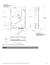
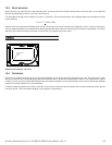
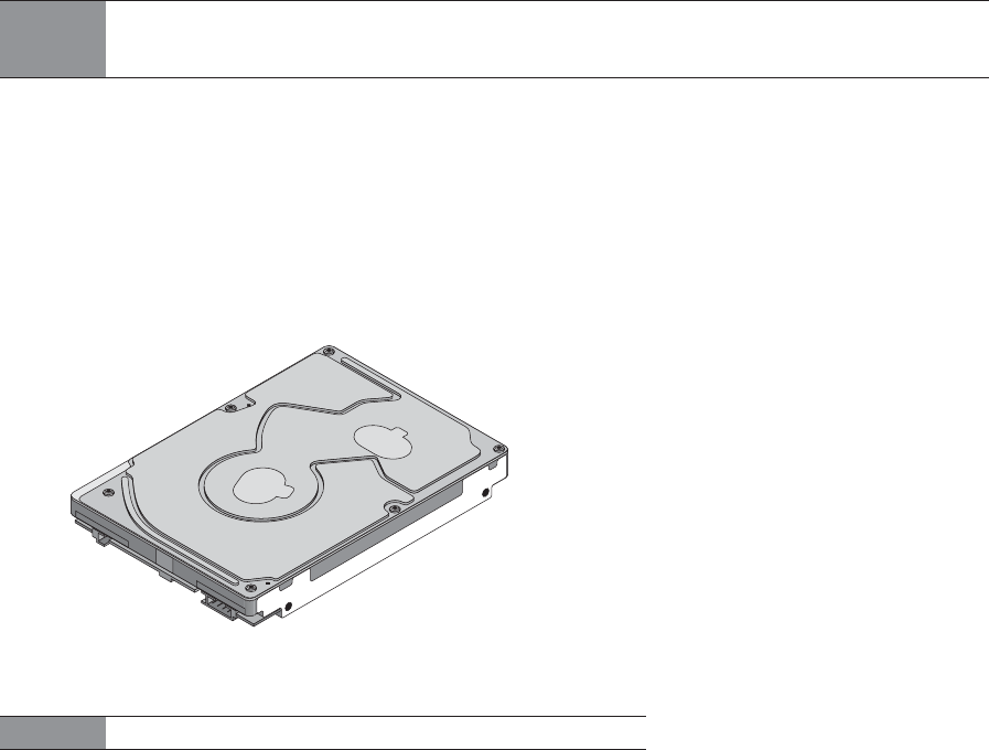
Figure 15. Physical interface
10.1 DRIVE ORIENTATION
The drive may be mounted in any orientation. All drive performance characterizations, however, have been done with the drive in
horizontal (discs level) and vertical (drive on its side) orientations, which are the two preferred mounting orientations.
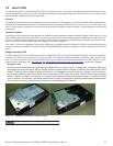
NOTE
SAS drives are designed to be attached to the host system without I/O or power cables. If users
intend the use the drive in a non-backplane host system, connecting the drive using high-quality
cables is acceptable as long as the I/O cable length does not exceed 4 meters (13.1 feet).
NOTE
Image is for reference only, may not represent actual drive.