


SEAGATE ENTERPRISE CAPACITY 3.5 HDD V4 SAS PRODUCT MANUAL, REV. A 62
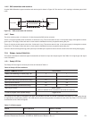
11.5.2 Differential signals
The drive SAS differential signals comply with the intra-enclosure (internal connector) requirements of the SAS standard.
Table 18 defines the general interface characteristics.
11.6 SAS-3 SPECIFICATION COMPLIANCE
Seagate SAS-3 compatible drives are compliant with the latest SAS-3 Specification (T10/BSR INCITS 519 rev. 06).
The main difference from SAS-2 is the Tx and Rx training that allows the host and drive to adjust the amplitude and emphasis values to the
channel. The receiver still employs Decision Feedback Equalizer (DFE) and Feed Forward Equalizer (FFE) circuitry to accomplish this
training.
1. A Decision Feedback Equalizer (DFE) which utilizes the standard SAS-2 training pattern transmitted during the SNW-3
training gap. The DFE circuit can derive an optimal equalization characteristic to compensate for many of the receive
losses in the system.
2. A Feed Forward Equalizer (FFE) optimized to provide balanced receive margins over a range of channels bounded by
the best and worst case channels as defined by the relevant ANSI standard.
11.7 ADDITIONAL INFORMATION
Please contact the Seagate representative for SAS electrical details, if required.
For more information about the Phy, Link, Transport, and Applications layers of the SAS interface, refer to the Seagate SAS Interface
Manual, part number 100293071.
For more information about the SCSI commands used by Seagate SAS drives, refer to the Seagate SCSI Commands Reference Manual,
part number 100293068.
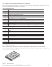
LED on, low I
OL
= 15 mA 0 V
OL
0.225 V
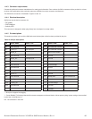
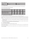
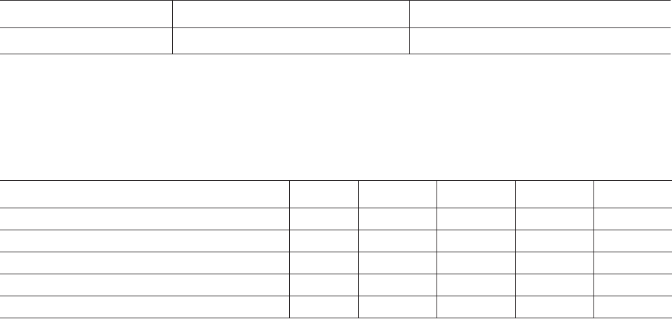
Table 18 General interface characteristics
CHARACTERISTIC UNITS 1.5GB/S 3.0GB/S 6.0GB/S 12 Gbps
Bit rate (nominal) Mbaud 1,500 3,000 6,000 12000
Unit interval (UI)(nominal) ps 666.6 333.3 166.6 83.3
Impedance (nominal, differential ) ohm 100 100 100 100
Transmitter transients, maximum V ± 1.2 ± 1.2 ± 1.2 ± 1.2
Receiver transients, maximum V ± 1.2 ± 1.2 ± 1.2 ± 1.2
Table 17 LED drive signal
STATE TEST CONDITION OUTPUT VOLTAGE