


ST43401N/ND, ST43402ND User’s Manual, Rev. B 27
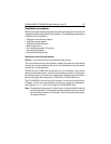
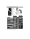
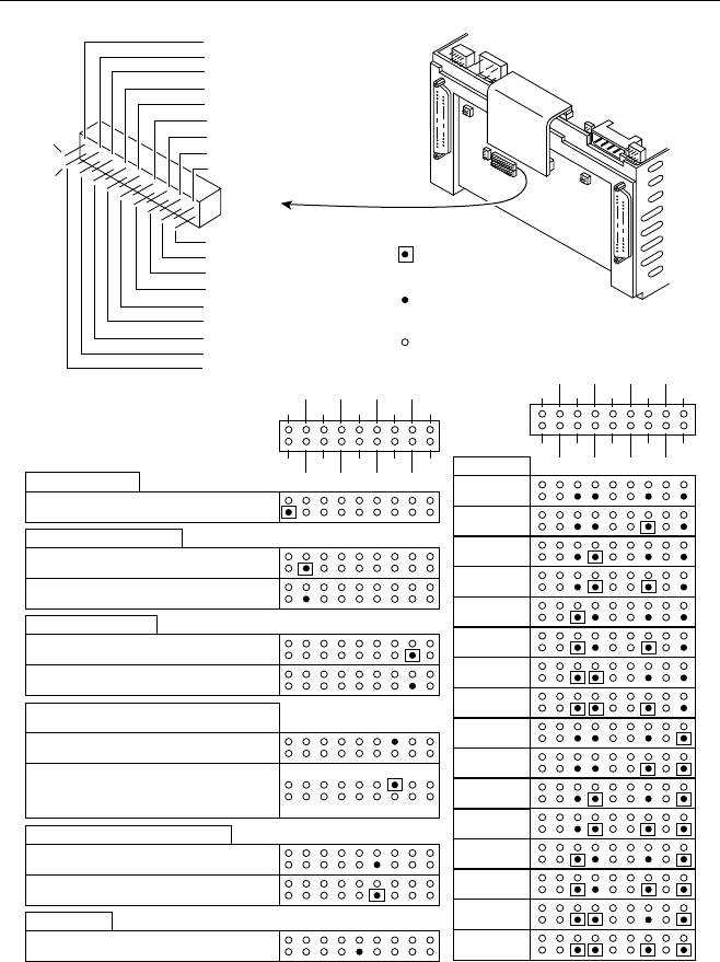
Manual Reset (MR)
RL SDO
L6 FL
Ground this pin to manually reset the SCSI board.
Remove ground after reset.
NAL4 PB
WPL PA
ST ID0
SBS PSS
ID3MR ID2
WRT ID1
Write Protect/Enable (WPL)
Write protect (disable writing)
Write enable (enable writing)
Panel Start/Stop (PSS)
Start spindle after the SCSI bus sends a
Start Unit command.
Start spindle according to the Spinup Delay
Option (SDO) pin on this I/O board.
Spinup Delay Option (SDO)
Used only if the PSS pin jumper is not connected.
Start turning spindle when power is applied.
Start spindle after a delay. The delay
(in seconds) is 10 seconds times the SCSI ID.
For example, when the SCSI ID is 4, a delay
of 40 seconds occurs before spinup starts.
SCSI Bus Select Mode Option (SBS)
Allow ports A and B to have different SCSI IDs.
Assign port A the same SCSI ID that port B has.
Self-Test (ST)
Use this pin to connect an indicator which will flash
when the drive is in the self-test mode of power up.
= Ground this pin to the
external device to activate
the option discussed
= Remove ground from this pin
using the external device to negate
this option
= Non-applicable pin (not relevant to the
option discussed)
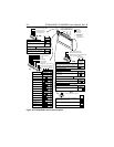
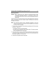
J10
LED 4 (L4)
Write Protect/Enable LED (WPL)
Port B Active LED (PB)
Port A Active LED (PA)
Ready LED (RL)
LED 6 N/A (L6)
Spinup Delay Option (SDO)
Fault LED (FL)
Not Assigned (NA)
ID 03 (ID3)
Panel Start/Stop (PSS)
ID 00 (ID0)
SCSI Bus Select (SBS)
Self-Test (ST)
ID 01 (ID1)
ID 02 (ID2)
Write Protect/Enable (WRT)
Manual Reset (MR)
Pin 2
Pin 1
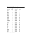
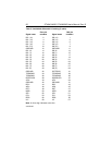
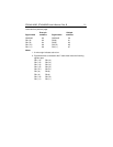
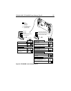
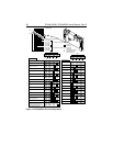
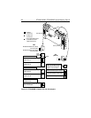
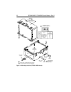
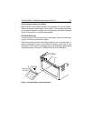
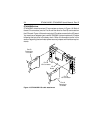
SCSI Bus ID
RL SDO
L6 FL
SCSI ID = 0
NAL4 PB
WPL PA
ST ID0
SBS PSS
ID3MR ID2
WRT ID1
SCSI ID = 1
SCSI ID = 2
SCSI ID = 3
SCSI ID = 4
SCSI ID = 5
SCSI ID = 6
SCSI ID = 7
SCSI ID = 8
SCSI ID = 9
SCSI ID = A
SCSI ID = B
SCSI ID = C
SCSI ID = D
SCSI ID = E
SCSI ID = F
Figure 11. ST43402ND I/O board J10 jumpers