


Elite 47 Installation Guide, Rev. B 29
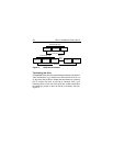
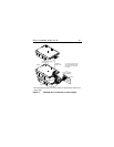
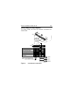
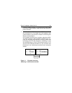
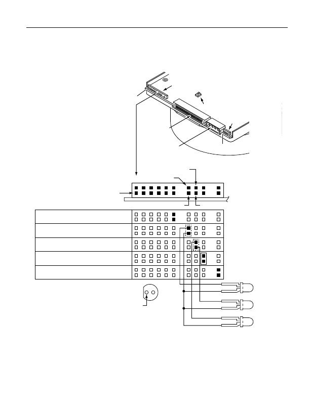
Active, Ready, and Fault indicators
The Active, Ready, and Fault LED indicator connections are
shown below.
Figure 9. LED indicator connections
J4A
Reserved
Active LED Connector
Fault/Ready LED Connector
Terminator Enabled (TE)
Active
Fault
Ready
Reserved
Note: On some LEDs the flat
side of indicator is cathode.
Pin 1
Pin 16
Pin 15 Pin 17
Pin 18
CATH
CATH
CATH
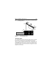
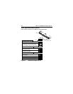
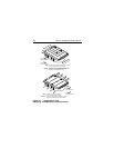
J01
J4B
J4A
J6
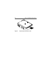
SCSI I/O
Connector
DC Power
Connector
Pin 1
Pin 1