


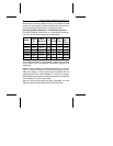
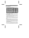
Drive configuration
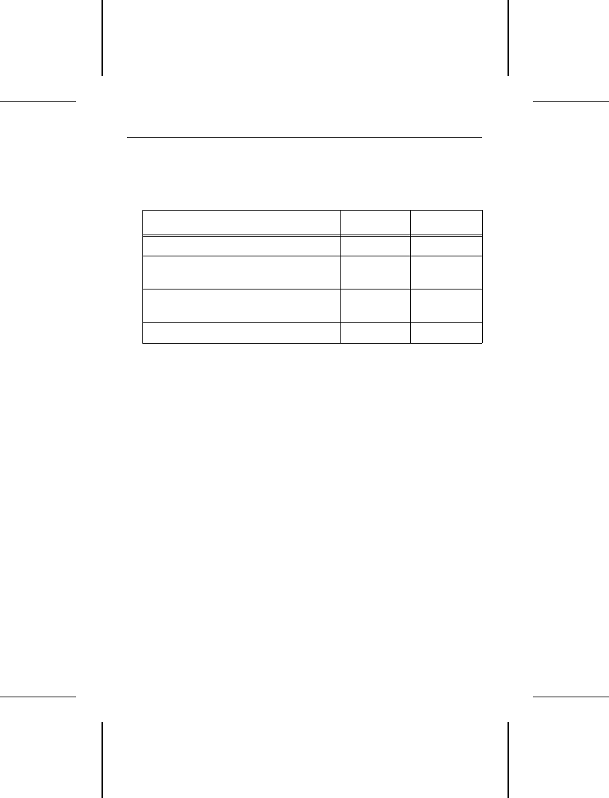
• Master/Slave configuration. Refer to the table below to con-
figure up to two drives on a single AT bus.
System Configuration Pins A-B Pins C-D
Drive is Master, no Slave present Removed Removed
Drive is Master,
Seagate Slave present*
Removed Installed
Drive is Slave to another
ST9144 Family AT Drive
Installed Removed
Reserved Positions (Do Not Use) Installed Installed
*Includes ST125A, ST138A, ST157A, ST1102A, ST1144A,
ST351A, ST3096A, ST3120A, ST3144A, ST9051A, ST9052A,
ST9077A, ST9096A, and ST9144A.
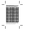
• Power connection. The ST9144 family drives use
+5 Volts DC power supplied to the drive through the interface
connector. Refer to the “44-Pin AT Interface Connector Assign-
ment” table for specific pin assignments.
Caution. The drive does not use +12 Volts DC power. Make
sure only +5 Volts DC is being supplied to the drive, as
specified in the “44-Pin AT Interface Connector Assignment”
table.
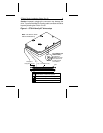
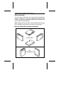
• Attach AT interface cable. Use a 44-pin AT interface connec-
tor cable with two rows of 22 female contacts on 0.079 inch
(2 mm) centers. Pin 20 has been removed on the connector
for keying purposes. A dual-drive system requires a 44-pin AT
interface daisy-chain cable. Most cables have a stripe down
one side to designate Pin 1.
Make sure Pin 1 on the interface cable connector is aligned to
Pin 1 on the drive interface connector and Pin 1 on the host
connector. The maximum cable length is 18 inches (457 mm).
8 ST9144 Family Installation Guide, Rev. B