


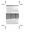
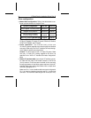

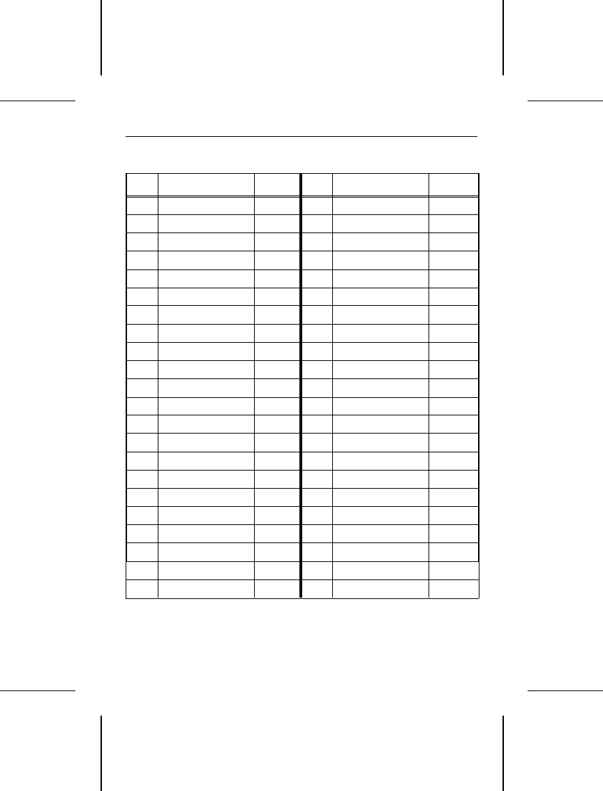
44-Pin AT interface connector assignments
Pin Signal I/O Pin Signal I/O
01 /Host Reset O 02 Ground
03 Host Data 7 I/O 04 Host Data 8 I/O
05 Host Data 6 I/O 06 Host Data 9 I/O
07 Host Data 5 I/O 08 Host Data 10 I/O
09 Host Data 4 I/O 10 Host Data 11 I/O
11 Host Data 3 I/O 12 Host Data 12 I/O
13 Host Data 2 I/O 14 Host Data 13 I/O
15 Host Data 1 I/O 16 Host Data 14 I/O
17 Host Data 0 I/O 18 Host Data 15 I/O
19 Ground 20 Key No Pin
21 Reserved 22 Ground
23 /HIOW O 24 Ground
25 /HIOR O 26 Ground
27 Reserved 28 Reserved
29 Reserved 30 Ground
31 IRQ 14 I 32 /Host IO16 (AT) I
33 Host ADDR 1 O 34 /PDIAG (16) Notes
35 Host ADDR 0 O 36 Host ADDR 2 O
37 /Host CS0 O 38 /Host CS1 O
39 /DASP Notes 40 Ground
41 +5 VDC (Logic) 42 +5 VDC (Motor)
43 Ground 44 Reserved
/ indicates active low signal. Direction is with respect to the host.
I indicates to the host, O indicates from the host. Reserved
pins/ground do not have direction.
/PDIAG and /DASP are used for
communication between master and slave drives.
ST9144 Family Installation Guide, Rev. B 11