


12-1
Chapter 12: Parameters
12
Chapter 12: Parameters
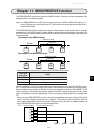
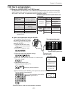
This chapter describes the parameters that can be set in the module. The parameter area is set in the
control module (CPU board). "12-3 How to set parameters."
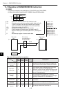
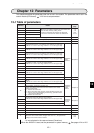
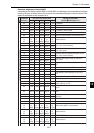
12-1 Table of parameters
Address
(8)
Details
Reference
page
00 IP address
When FF
(H)
is written to address 03, the module will
enter the data memory setting mode.
- Enter the parameter file address at addresses
00 and 01. Enter the file number at address 02.
7-5
7-8
12-3
15-13
01 IP address
02 IP address
03 IP address, node number
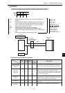
04 Token monitor timing => See next page 8-13
05 Interval between frames (normally set to 0) 15-22
06 to 07 Reserved area -
10
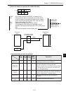
Data transmission Area 1 top address (word address) for this node.
- Address 10 is for the lower digit. Address 11 is for the upper digit.
Related to
cyclic
transfers
Chapter 8
11
12
Data length (word) of Area 1 for this node.
- Address 12 is for the lower digit. Address 13 is for the upper digit.
13
14
Data transmission Area 2 top address (word address) for this node.
- Address 14 is for the lower digit. Address 15 is for the upper digit.
15
16
Data length (word) of Area 2 for this node.
- Address 16 is for the lower digit. Address 17 is for the upper digit.
17
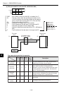
20
Top address of Area 1 on the PC (word address)
- Address 20 is for the lower digit. Address 21 is for the upper digit.
21
22 Area 1 file number on the PC
23 Reserved area
24
Top address of Area 2 on the PC (word address)
- Address 24 is for the lower digit. Address 25 is for the upper digit.
25
26 Area 2 file number on the PC
27 Reserved area -
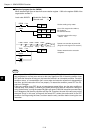
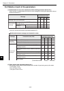
30
Top address of the communication control area on the PC (word
address)
- Address 30 is for the lower digit. Address 31 is for the upper digit.
Related to
communi-
cation
control
Chapter 10
31
32 Communication control area's file number on the PC
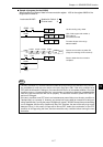
33
Communication control area transfer type
- Specify the address to transfer from the module to the control
module (CPU board)
00
(H)
: Transfer all of the area
80
(H)
: Does not transfer data from the communication transfer area.
81
(H)
: Transfer only the participating node list flag, operation status
flag, and error status flag.
83
(H)
: Transfer all of the area.
34
Transmission buffer top address (word address)
- Address 34 is for the lower digit. Address 35 is for the upper digit.
Related to
message
transfer
Chapter 9
35
36 Transmission buffer file number
37 Enable/disable use of the transmission buffer => See next page
40 to 51 Node name (10 ASCII characters) -
52 to 57 Reserved area -
60 Timeout time for the SEND/RECEIVE instruction (0.1 to 25.5 sec.). 11-8
61 to 76 Reserved area -
77
Start switch
- When the value of this switch changes from 00 to 01
(H)
, the parameters
settings are transferred to the module.
8-3
9-2
- Do not write data in the reserved areas (5 locations).
When the JW-50FL is used, set the parameters in system memory. See pages 12-4 to 12-5.