


12-3
Chapter 12: Parameters
12
12-3 How to set parameters
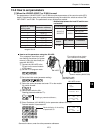
[1] When the JW-20FL5/20FLT or Z-366J is used
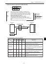
Set parameters of JW-20FL5/20FLT and Z-336J as optional parameters of the control module (CPU
board). Determine the area of the optional parameters using the module No. switch set value of JW-
20FL5/20FLT and Z-336J. The parameters occupy 64 bytes per module.
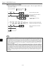
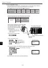
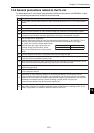
How to set the parameters using the JW-14PG
This paragraph describes param-
eter setting procedures (in system
memory) using the hand-held pro-
grammer JW-14PG.
1 Connect the JW-14PG to the
PG port on the control module
(CPU board.)
2 Set the PC to program mode.
3 Set to the initial mode (parameter setting).
4 Select the option parameter and enter "2" for the module
No. switch number.
5 Rewrite start switch to 00(H).
Reading parameter address 77(8).
6 Enter IP address (192.168.250.3) for the parameter address 00 to 03(8).
Decimal notation of parameter 00.
Same as the above, enter the other parameter addresses.
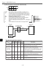
Connection cable
(JW-22KC/24KC)
JW-14PG
Control module (JW-33CUH)
JW-20FL5
(The modules shown below
are installation examples)
Decimal display of the setting
of parameter 00
JW-14PG screen
75 HEX 00
76 HEX 00
I Parameter 0 - SW: 2
>77 HEX 00
01 DCM 168
02 DCM 250
I Parameter
>03 DCM 003
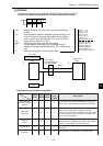
FL-net module Host PC Control module
JW-20FL5
JW-20FLT
JW20H JW-21CU/22CU
JW30H
JW-31CUH1
JW-32CUH1
JW-33CUH1/2/3
FL-net
board
Host J-board CPU board
Z-336J
Z-300 series Z-311J/312J/313J
Z-500 series Z-511J
- Relationship between the host PC and the con-
trol module
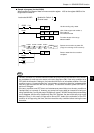
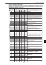
Note: Do not set switch SW3 outside the
range of 0 to 6.
Module No. switch
setting value
Parameter address
(H)
000to77
100to77
200to77
300to77
400to77
500to77
600to77
Reading a prameter address
(H)
I Parameter 0 - SW: 2
I Parameter
0) I/O
1) Option