


55
Appendix
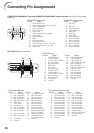
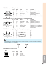
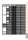
RS-232C Terminal: mini DIN 9 pin female connector
RD
SD
SG
RS
CS
Signal Name
8
9
6
5
21
4
3
7
Pin No.
1.
2.
3.
4.
5.
6.
7.
8.
9.
I/O Reference
Not connected
Connected to internal circuit
Connected to internal circuit
Not connected
Connected to internal circuit
Not connected
Connected to CS in internal circuit
Connected to RS in internal circuit
Not connected
Receive Data
Send Data
Signal Ground
Request to Send
Clear to Send
Input
Output
RS-232C Terminal: D-sub 9 pin male connector of the DIN-D-sub RS-232C adaptor
RD
SD
SG
RS
CS
Signal NamePin No.
1.
2.
3.
4.
5.
6.
7.
8.
9.
I/O Reference
Not connected
Connected to internal circuit
Connected to internal circuit
Not connected
Connected to internal circuit
Not connected
Connected to CS in internal circuit
Connected to RS in internal circuit
Not connected
Receive Data
Send Data
Signal Ground
Request to Send
Clear to Send
Input
Output
15
69
CD
RD
SD
ER
SG
DR
RS
CS
CI
SignalPin No.
1.
2.
3.
4.
5.
6.
7.
8.
9.
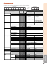
RS-232C Cable recommended connection: D-sub 9 pin female connector
CD
RD
SD
ER
SG
DR
RS
CS
CI
SignalPin No.
1.
2.
3.
4.
5.
6.
7.
8.
9.
51
96
• Depending on the controlling device used, it may be necessary to connect Pin 4 and Pin 6 on the
controlling device (e.g. computer).
Note
Projector
Pin No.
4
5
6
Computer
Pin No.
4
5
6
12
43
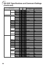
USB Terminal: Type B USB connector
VCC
USB–
USB+
SG
Signal NamePin No.
1.
2.
3.
4.
USB power
USB data–
USB data+
Signal Ground