


-2
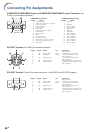
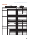
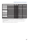
Connecting Pin Assignments
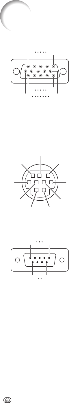
COMPUTER/COMPONENT input and COMPUTER/COMPONENT output Terminals: mini
D-sub 15 pin female connector
COMPUTER Input/Output COMPONENT Input/Output
Pin No. Signal Pin No. Signal
1.
2.
3.
4.
5.
6.
7.
8.
9.
10.
11.
12.
13.
14.
15.
Video input (red)
Video input (green/sync on green)
Video input (blue)
Not connected
Not connected
Earth (red)
Earth (green/sync on green)
Earth (blue)
Not connected
GND
Not connected
Bi-directional data
Horizontal sync signal: TTL level
Vertical sync signal: TTL level
Data clock
1.
2.
3.
4.
5.
6.
7.
8.
9.
10.
11.
12.
13.
14.
15.
PR (CR)
Y
PB (CB)
Not connected
Not connected
Earth (PR)
Earth (Y)
Earth (PB)
Not connected
Not connected
Not connected
Not connected
Not connected
Not connected
Not connected
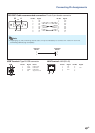
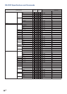
RS-232C Terminal: mini DIN 9 pin female connector
Pin No. Signal Name I/O Reference
1.
2.
3.
4.
5.
6.
7.
8.
9.
RD
SD
SG
RS
CS
Receive Data
Send Data
Signal Ground
Request to Send
Clear to Send
Input
Output
Not connected
Connected to internal circuit
Connected to internal circuit
Not connected
Connected to internal circuit
Not connected
Connected to CS in internal circuit
Connected to RS in internal circuit
Not connected
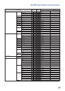
RS-232C Terminal: D-sub 9 pin male connector of the DIN-D-sub RS-232C adaptor
Pin No. Signal Name I/O Reference
1.
2.
3.
4.
5.
6.
7.
8.
9.
RD
SD
SG
RS
CS
Receive Data
Send Data
Signal Ground
Request to Send
Clear to Send
Input
Output
Not connected
Connected to internal circuit
Connected to internal circuit
Not connected
Connected to internal circuit
Not connected
Connected to CS in internal circuit
Connected to RS in internal circuit
Not connected
5
10
15
1
11
6
5
10
15
1
11
6
8
9
6
5
21
4
3
7
8
9
6
5
21
4
3
7
15
69
15
69