


11
English
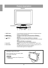
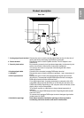
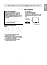
Rear view
7
8
9
0
q
w
e
e
Product description
7. Analog signal input terminal Remove the cover to see the analog signal input terminal. At the time of
leaving the factory the analog signal cable is connected.
8. Power terminal Remove the cover to see the power terminal. The AC adapter is con-
nected here.
9. Security lock anchor By connecting a security lock (purchased separately) to the security lock
anchor, the monitor is fixed so that it cannot be transported.
The security slot works in conjunction with Kensington Micro Saver
Security Systems.
10.Analog signal cable Connects to the computer's analog RGB output terminal.
11.USB port Remove the cover to see the USB port (upstream: 1 port, downstream: 2
ports).
12.DVI-I input terminal Remove the cover to locate the digital/analogue signal input terminal
(DVI-I29 pin). The computer’s digital RGB output terminal or analogue
RGB output terminal can be connected here.
For a digital signal input: It can be connected to a computer with a DVI-
compatible output terminal (DVI-D24 pin or DVI-I29 pin) and which has
SXGA output ability. Depending on the computer to be connected, correct
display may or may not be possible.
To be able to connect, a cable that is to be purchased separately is
required.
To connect to a digital RGB output terminal: Digital signal cable (model
name: NL-C01E)
To connect to an analogue RGB output terminal: Analogue signal cable
(model name: NL-C02E)
13.Ventilation openings Note: Never block the ventilation openings as this may lead to
overheating inside the monitor and result in malfunction.