IM-215 Rev-A.1 Series Innova-Switch™ Page 22 of 42
4.0 OPERATION AND CALIBRATION OF THE Innova-Switch
™
FS4200 SWITCH FOR
FLOW APPLICATIONS
4.1 Pre-Operational Check
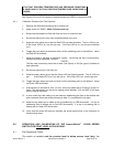
With the switch installed and process conditions at no-flow, the following procedure
can be used to verify preliminary operation.
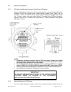
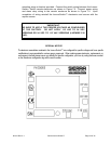
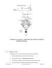
4.1.1 Remove the instrument enclosure cover by turning counter clockwise (ccw) to expose
the Innova-Switch™ Switch electronics.
4.1.2 Turn on power at its source.
4.1.3 Observe that either the red or green LED comes on.
4.1.4 If neither lamp illuminates refer to the trouble shooting Section, 6.2.
4.2 L.E.D. and Relay Status Logic (Fail-safe)
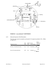
4.2.1 The L.E.D.s (Red; Green) are an indication of the sensors status (ie. flow below the
setpoint or flow above the set point) and are not affected by the position of the failsafe
jumper J-2. The failsafe jumper J-2 changes the relay activation status allowing the
user to select the failsafe power off condition most appropriate to the application.
Refer to the tables below that show the logic conditions between the sensors, L.E.D.
lights, relay coil and contacts for each position of the failsafe jumper J-2.
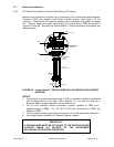
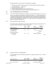
4.2.2 Normal Operation (as set at factory)
The switch comes configured from the factory with the following operation with the J-2
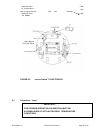
jumper in the B(2-3) position. (Refer to Figure 8.0.)
RELAY
RED GREEN RELAY CONTACT
SENSOR STATUS LED LED COIL STATUS STATUS
o NC
No Flow or Flow Below Set Point ON OFF Activated
o NO
o NC
Flow or Flow Above Set Point OFF ON Deactivated
o NO


