


MAINTENANCE INSTRUCTIONS
4.2
maintenance, the exposure device must be withdrawn from service until repairs are
accomplished and the results of subsequent operational tests and inspection are satisfactory.
Inspect the radiography system for the following using a ‘satisfactory’ or ‘deficient’ criteria:
1 Survey the surface of the exposure device to ensure the measurable dose/rate is less than
200mR/hr (2mSv/hr). Remove the device from service if the dose/rate exceeds this limit.
Contact AEA Technology QSA for guidance.
2 Ensure the metal identification tag for the radioisotope is legible and securely fastened to
the exposure device. Do not cover the tag with any other labels.
3 Ensure the label containing the device model number, serial number, Type B certification
number and the trefoil with the warning ‘Caution or Danger, Radioactive Material’ is legible
from a distance of 3ft (approximately 1m) and securely fastened to the exposure device.
Do not cover the required warnings with any other labels. Ensure the labels applied for
transportation are legible.
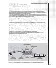
4 Check the welded stainless steel end plates of the exposure device for weld failure
(cracks, etc.) behind the back plate (locking mechanism) or the front plate (outlet port).
Ensure the handle, the bottom contact surfaces and the sides comprising the plastic jacket
of the exposure device are intact. Check the bottom contact surfaces of the jacket to ensure
the contact area is not excessively worn allowing contact of the stainless steel body with
the work surface. If any deficiencies are found during this inspection, repairs can be
accomplished at an AEA Technology QSA service center.
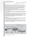
5 Check the outlet port for proper function by attaching and removing a source guide tube.
The operation should be smooth and resistance free. If there is any resistance or ‘crunchy’
feeling noticed during attachment or removal of the source guide tube or during movement
of the outlet port cover, this indicates excessive amounts of sand or dirt within the
mechanism. The outlet port mechanism must be removed, cleaned and lubricated according
to the complete service instructions.
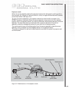
6 Check the locking mechanism and plunger lock to verify attachment and operation.
Grasp the entire mechanism with one hand and attempt to shift the mechanism.
Retaining screws that have been loosened from excessive vibration or improper maintenance
will allow the movement of the locking mechanism during this check. Loose screws must be
tightened according to the annual maintenance requirements prior to use or transport.
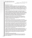
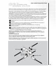
7 Use the Model 550 NO GO gauge to check for wear on the remote control cable
connector and the source assembly connector. Replace components that fail any of
these tests.
8 Operationally check the locking mechanism and then the function of the entire system
during the first radiographic exposure of the work shift while within a restricted area.
Operation of the radiographic system verifies both the locking mechanism and entire system
operates smoothly and freely. If operation is faulty, remove the exposure device from service
and perform the complete annual maintenance.
Routine (quarterly) maintenance records
Records of all equipment inspected and maintained during the routine maintenance must be
recorded. Records should indicate:
●
The date of inspection and maintenance.
●
Name of the qualified individual performing the required inspections.
●
Problems found and maintenance or repairs performed.
●
Model number and serial number of the exposure device.
●
Associated equipment that was inspected and maintained.
●
Part numbers and associated lot numbers or serial numbers of replacement
parts installed.