


Si2493/57/34/15/04
Global ISOmodem-EVB
6 Rev. 0.6
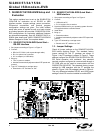
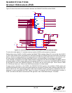
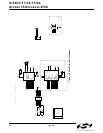
Figure 13 on page 17 and Figure 15 on page 19 for the
reset circuit schematic.
2.1.3. DS1818
The DS1818 is a small, low-cost device that monitors
the voltage on V
D
and an external reset pushbutton. If
V
D
drops below 3.0 V, the DS1818 provides a 220 ms
active-low reset pulse. On powerup, the DS1818 also
outputs an active low reset pulse for 220 ms after V
D
reaches 90% of the nominal 3.3 V value. The DS1818
outputs a 220 ms reset pulse any time the power supply
voltage exceeds the 3.3 V ±10% window.
2.1.4. Manual Reset
The manual reset switch (S1) performs a power-on
reset. This resets the Si2493/57/34/15/04 to factory
defaults without turning off power. If S1 is used in
conjunction with U3, pressing S1 activates the reset
monitor in the DS1818 and produces a 220 ms active
low reset pulse.
2.1.5. EEPROM Enable (FT Only)
Connecting JP10 enables the optional EEPROM, U9.
See “AN93: Si2457/Si2434/Si2415/Si2404 Modem
Designer’s Guide” for programming details.
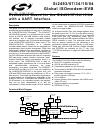
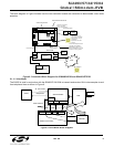
2.1.6. Interface Selection
The serial interface of the Si2493/57/34/15/04-EVB can
be connected to a computer, terminal, embedded
system, or any other data terminal equipment (DTE) via
a standard RS-232 interface, USB interface, or through
a direct TTL serial interface.
The Si2493/57/34/15/04 can be tested as a standard
data modem by connecting the Si2493/57/34/15/04-
EVB to a personal computer or other DTE power supply
and a phone line. A PC can communicate with the
Si2493/57/34/15/04-EVB using a standard terminal
program, such as HyperTerm or ProComm.
Jumper settings determine how the Si2493/57/34/15/
04-EVB is connected to the DTE. Table 1 lists the
interface controlled by each motherboard jumper. See
Figure 14 on page 18 and Figure 24 on page 28.
2.1.7. RS-232 Interface
This operation mode uses the standard factory jumper
settings illustrated in Figure 1 on page 2. The Maxim
MAX3237 transceiver interfaces directly with the TTL
levels available at the serial interface of the Si2493/57/
34/15/04 and, using internal charge pumps, makes
these signals compatible with the RS-232 standard. The
RS-232 transceiver on the Si2493/57/34/15/04-EVB can
communicate at rates between 300 bps and 1 Mbps.
This simplifies the connection to PCs and other data
terminal equipment (DTE). The signals available on the
Si2493/57/34/15/04-EVB serial interface (DB9
connector) are listed in Table 2.
2.1.8. USB Interface
The USB cable connects to J5 on the motherboard and
provides both data and power. Installing a jumper on
JP5 enables the USB interface and disables the RS-232
interface. The USB interface is provided by U5. A USB
driver for this chip is available for most PC and MAC
operating systems on the CD.
2.1.9. Direct Access Interface
The motherboard supplies power through J3, J4, or
USB, power-on reset, and an RJ-11 jack for the modem.
The direct access interface (JP3) is used to connect the
motherboard to an embedded system. JP3 provides
access to all Si2493/57/34/15/04 signals available on
the daughter card. It is necessary to install a jumper on
JP8 to disable both the RS-232 and USB interface and
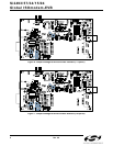
prevent signal contention. Leave the jumper between
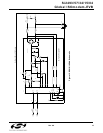
JP7 pins 1 and 2. Figures 6 and 7 illustrate the jumper
settings required for the direct access mode using the
motherboard.
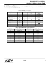
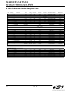
Table 1. Interface Selection Jumpers
Jumper Function
JP1 Daughter Card Digital Connector.
JP2 Daughter Card Phone Line Connector.
JP3 Direct Access Header.
JP4 PCM Interface.
JP5 USB Enable (RS-232 Disable).
JP6 Options.
JP7 3.3 V Power for Daughter Card.
JP8 Disable both RS-232 and USB.
JP9 Autobaud disable.
JP10 EEPROM enable.
JP11 Enable 27 MHz Clock option.
JP12 Not used.
JP13 On-board speaker enable.