


Si2493/57/34/15/04
Global ISOmodem-EVB
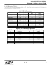
Rev. 0.6 9
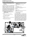
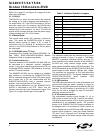
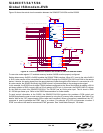
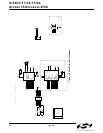
The block diagram in Figure 8 shows how the two evaluation boards are connected to demonstrate voice mode
operation.
Figure 8. Connection Block Diagram for Si3000SSI-EVB and Si24XXURT-EVB
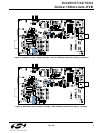
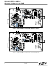
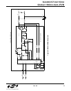
2.1.11. Voice Mode
The Si3000 is used in conjunction with the Si2493/57/34/15/04 to transmit and receive 16-bit voice samples to and
from telephone lines as shown in Figure 9.
Figure 9. Voice Mode Block Diagram
Use telephone in off
hook position to emulate
600 Ω Handset. Not all
handsets are
implemented as 2 wire
anymore.
Si24xx-EVB
Direct Connection
Connect the telephone to RJ11
(right side) on the Si3000
Daughterboard, NOT to the
RJ11 on motherboard. Look for
silk screen marking "HDST".
COM 1
Windows PC
WAN
Si3000 Daughterboard
Telephone
JP4
J
6
12V
GND
External
+12V
Supply
Si3000SSI-EVB Motherboard
J6 of Daughterboard
Leave J3 unconnected.
Power is provided
through JP 6 connector.
Note M1 and M0
jumper settings.
Power
Adapter
JP4
RS232 Si24xx-DC
J4
RJ11
Speaker
Mic
Line
In
Line
Out
RJ11
JP6
SW3
JP4
SW2
JP5
1
2
2
1
J
3
Si2457 Modem
Si3000 Voice Codec
DAA
Handset
HOST
AT commands
Responses
2-wire
SDISDO
FSYNC MCLK
CLKOUT
SDI
SDO
FSYNC
TDMA Interface