


99-00539-00 Rev B0 Installing an X-Port 20 Switch in a 2000i 7
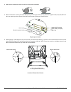
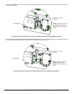
5. Locate the tie-wrapped bundle of cables running along the underside of the cabinet. In this bundle is a video cable (labeled RBG 1
IN) that connects directly to the RGB IN port on the projector. Disconnect this cable from the back of the projector, carefully cut the
tie wraps that hold the bundle together with a pair of wire cutters or sturdy scissors, and connect the cable to the Video IN port on the
top card of the X-Port 20 switch.
Connecting the RBG 1 IN Cable to the X-Port 20 Switch
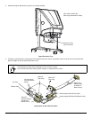
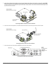
6. Connect one end of the supplied 6' (1.8 m) HD15 cable to the Video OUT port on the top card of the X-Port 20 switch.
Connecting the Video Cable to the X-Port 20 Switch
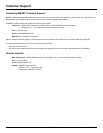
7. Connect the other end of this cable to the RGB IN port at the back of the projector.
Connecting the Video Cable to the Projector
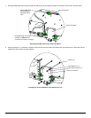
Connect RBG1 IN
Cable Here
X-Port 20 Switch
(Cables Not Shown for Clarity)
Video IN Port
Connect the Supplied
HD15 Cable Here
X-Port 20 Switch
(Cables Not Shown for Clarity)
Video OUT Port
VIDEO
IN
R
AUDIO
L/MONO
AUDIO OUT
S-VIDEO
IN
R
AUDIO
PC CONTROL
RGB OUT
L/MONO
RGB IN
AUDIO
USB(PC)
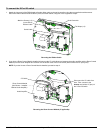
RGB IN Port
NOTE:
Connection panel
is depicted
upside down (as
installed)