


31
Contents
Appendix B
Device Specific Hints
SMC Dialogue Plus
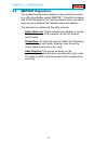
The SMC Dialogue Plus does not support Datalinks, therefore the
configuration of SW1-7 and 8 should not include any of the Datalinks
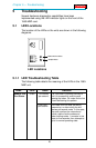
Enabled. If a Datalink is enabled, the SCANport Status LED will toggle,
indicating an error in the SCANport communications.
The version of SMC which was tested (Rev 1.05) had 88 parameters.
Each parameter was accessible in the Modbus register listing shown in
Appendix A. Note that if one of the 88 parameters is to be changed from
a host that the host must enable the EEPROM Storage function by
writing a 2 into the Parameter Management parameter (Parameter 17 -
Modbus address 40117 ).
SMP 3
The SMP3 does not support Datalinks, therefore the configuration of
Datalinks should not include any of the Datalinks Enabled. If a Datalink
is enabled, the SCANport Status LED will toggle, indicating an error in
the SCANport communications.
The 1560-MBP is able to read all of the parameters out of the SMP3
unit.
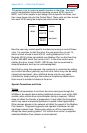
Variable Speed Drives
In order to enable Frequency control from the 1560-MBP, the drive
parameter FREQUENCY SELECT 2 must be configured for the
appropriate Adapter ID representing the 1560-MBP module. This will
normally be Adaptor #2, unless a SCANport expander is being used (in
which case this Adaptor number will be based on the port the 1560-MBP
is plugged into).
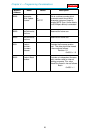
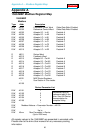
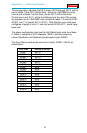
Setting up the Adaptor I/O - Datalinks Out
Selects the parameter values which will be made available from
the 1560-MBP via Global Data Out. Placement of the values in
the 1560-MBP is referenced in Appendix A.
Appendix B — Device Specific Hints
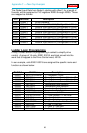
Data Out
Image
Suggested
Parameter Description
A1
A2
54
1
Output Power
DC Bus Voltage
B1
B2
23
53
Output Current
Output Volts