


36
Contents
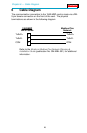
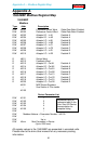
Appendix C — Peer Cop Example
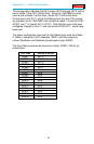
The Global Input Data from Node 6, starting with offset 1 for a length of
9 words, will be assigned to PLC registers 40200 through 40209. These
are mapped as follows:
PLC RefOffset Description
40200 Offset 1 Drive Feedback
40201 Offset 2 Datalink Input Word A1 (Configurable in Drive)
40202 Offset 3 Datalink Input Word A2 (Configurable in Drive)
40203 Offset 4 Datalink Input Word B1 (Configurable in Drive)
40204 Offset 5 Datalink Input Word B2 (Configurable in Drive)
40205 Offset 6 Datalink Input Word C1 (Configurable in Drive)
40206 Offset 7 Datalink Input Word C2 (Configurable in Drive)
40207 Offset 8 Datalink Input Word D1 (Configurable in Drive)
40208 Offset 9 Datalink Input Word D2 (Configurable in Drive)
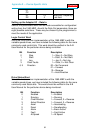
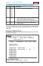
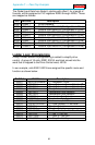
Ladder Logic Programming
Finally, a small amount of programming is added to simplify drive
control. A group of 16 coils, 00001-00016, are block moved into the
word that is mapped to the Drive Control word, 40100.
In our example, coils 00001-00016 are assigned the specific name and
function as shown below:
PLC Ref PLC Name Description
000001 MOP DECREMENT 1 = Decrement, 0=Not
000002 REF SEL1 Binary Reference Source Selection 2
0
000003 REF SEL2 Binary Reference Source Selection 2
1
000004 REF SEL3 Binary Reference Source Selection 2
2
000005 DEC SEL1 Decellaration Rate Selection
000006 DEC SEL2 Decellaration Rate Selection
000007 ACC SEL1 Accelaration Rate Selection
000008 ACC SEL2 Accelaration Rate Selection
000009 MOP INCREMENT 1 = Increment, 0=NOT
000010 LOCAL LOCKOUT 1 = Local Lockout, 0 = Not Local
000011 DIR SEL1 Direction Selection
000012 DIR SEL2 Direction Selection
000013 DRV RESET 1 = Clear Faults, 0 = Not Clear Faults
000014 DRV JOG 1 = Jog, 0 = Not Jog
000015 DRV START 1 = Start, 0 = Not Start
000016 DRV STOP 1 = Stop, 0 = Not Stop