


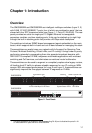

Description of Hardware
1-5
1
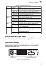
Optional Redundant Power Supply
The switch supports an optional Redundant Power Supply (RPS), that can supply
power to the switch in the event the internal power supply fails.
Power Supply Sockets
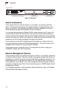
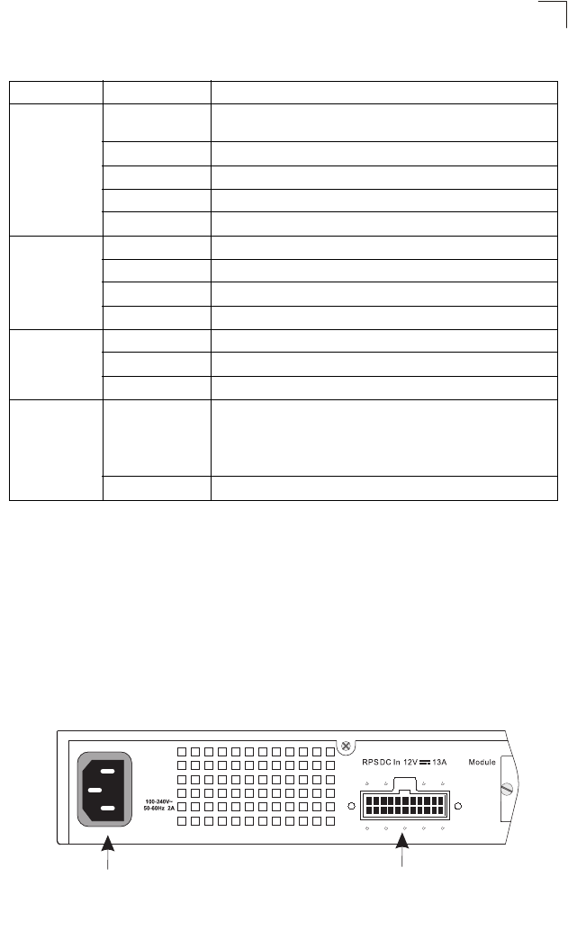
There are two power sockets on the rear panel of each switch. The standard power
socket is for the AC power cord. The socket labeled “RPS” is for the optional
Redundant Power Supply (RPS).
Figure 1-5 Power Supply Sockets
Stack Master Green Switch is the Master unit of the stack. State may include topology
discovery, IP assignment, or normal operations.
Flashing Green Switch is the Master unit of the stack, system is initializing.
Amber Switch is operating as a Slave unit in the stack.
Flashing Amber System in Master arbitration/election state.
Off System in standalone mode.
Stack Link Green Uplink and downlink operating normally.
Flashing Green Uplink has failed.
Flashing Amber Downlink has failed.
Off No stacking link present.
Module Green An expansion module is installed and operating normally.
Amber An expansion module is installed but has failed.
Off There is no module installed.
Stack ID 1-8 Indicates the switch stack ID.
The Master unit is numbered 1. (Note that If the master unit fails
and a backup unit takes over, the stack IDs do not change.)
Slave units are numbered 2-8.
Off In standalone mode.
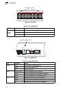
Table 1-2 System Status LEDs (Continued)
LED Condition Status
Power Socket
Redundant Power Socket