


3-9
Connecting to the Console Port
3
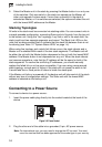
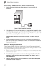
3. Check the front-panel LEDs as the device is powered on to be sure the Power
LED is on. If not, check that the power cable is correctly plugged in.
4. If you have purchased a Redundant Power Supply, connect it to the switch and
to an AC power source now, following the instructions included with the
package.
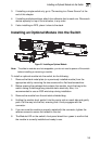
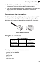
Connecting to the Console Port
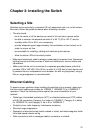
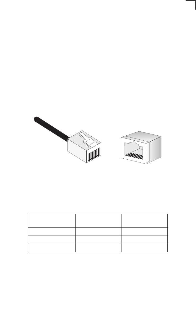
The RJ-45 serial port on the switch’s front panel is used to connect to the switch for
out-of-band console configuration. The on-board configuration program can be
accessed from a terminal or a PC running a terminal emulation program. The pin
assignments used to connect to the serial port are provided in the following table.
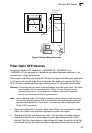
Figure 3-9 Serial Port (RJ-45) Pin-Out
Wiring Map for Serial Cable
The serial port’s configuration requirements are as follows:
• Default Baud rate—9,600 bps
• Character Size—8 Characters
• Parity—None
• Stop bit—One
• Data bits—8
• Flow control—none
Table 3-1 Serial Cable Wiring
Switch’s 8-Pin
Serial Port
Null Modem PC’s 9-Pin
DTE Port
6 RXD (receive data) <---------------------------- 3 TXD (transmit data)
3 TXD (transmit data) -----------------------------> 2 RXD (receive data)
5 SGND (signal ground) ------------------------------ 5 SGND (signal ground)
No other pins are used.
8
1
1
8