


35
Chapter 2 Menu
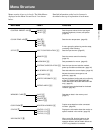
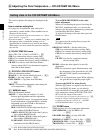
Data pertaining to the input signals are set with the
INPUT CONFIGURATION menu.
When a channel number (1 to 90) is entered with the
numeric keypad, it is then possible to set which input
connector on the rear panel will be assigned to that
channel number, and select the type of signal that will
be connected.
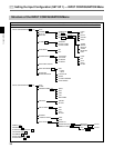
The following data can be set with the INPUT
CONFIGURATION menu.
• Assigning the signal FORMAT
• Assigning the SLOT NO
• Assigning the INPUT NO (input connector
number)
• Selecting the YC SEP (separation) filter
• Selecting the SYNC MODE
• Selecting the SCREEN MODE
• Selecting the SAFE AREA DISPLAY
• Setting the SAVE AREA MODE
• Activating/deactivating the APERTURE
adjustment
• Assigning the APERTURE VALUE
• Turning on/off the FILTER operation for
monochrome display
• Assigning CHANNEL NAME
• Selecting the picture CONTROL settings
• Setting the COLOR TEMP (temperature)
• Adjusting H PHASE
• Assigning the number of active scanning lines of
1125/60I SYSTEM
• COPYing FROM other data
Note
Data copy is impossible between monitors other than
BVM-DxxE/DxxF series.
Channels 91 to 99 assignment
The channel numbers from 91 to 99 are assigned to
internal signals.
091: PLUGE signal (Picture Line Up Generating
Equipment)
092: 20% gray signal
093: 100% white signal
094: five-step gray scale signal
095: cross hatch signal
096: cross hatch signal
097: dot signal
098: cross hatch signal
099: 0% black signal
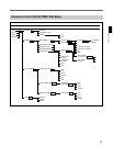
Overview
Assigning slot and connector numbers
Set which input connector on which slot will be
assigned to the current channel. The slots are numbered
from the left, as seen when facing the rear panel, with
the REMOTE connectors slot being number 1, the
input option slots numbers 2 to 5, and the analog input
connectors slot being number 6. The connectors for
each slot are numbered 1 to 6 (from the top).
Assigning the signal type and format
The signal type and format which can be assigned to
each channel number vary, depending on what
adaptors (not supplied) are installed in the rear panel.
To assign serial digital signals
Serial digital signals can be assigned to the serial
digital input connectors on the BKM-20D/21D/22X/
41HD/42HD adaptors.
You need to install one of the BKM-20D (for
component signals only), BKM-21D, BKM-41HD or
BKM-42HD adaptors with a serial digital signal
decoder to the rear panel of the monitor.
To assign analog composite signals
Analog composite signals can be assigned to any
analog input connectors on the BKM-20D/21D/22X or
any input connectors on the BKM-24N/25P/26M/27T/
28X/48X.
You need to install one of the following decoder
adaptors.
To assign NTSC signals: BKM-21D/24N/27T
To assign PAL signals: BKM-21D/25P/27T
To assign PAL-M signals: BKM-26M
To assign SECAM signals: BKM-27T
To assign Y/C signals
Y/C signals can be assigned to any input connectors on
the BKM-24N/25P/26M/27T/28X/48X.
You need to install one of the following decoder
adaptors.
To assign NTSC signals: BKM-24N/27T
To assign PAL signals: BKM-25P/27T
To assign PAL-M signals: BKM-26M
To assign analog component or RGB signals
Analog component and RGB signals can be assigned
to any input connectors except the serial digital signal
input connectors on the BKM-20D/21D/22X/41HD/
42HD.
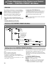
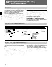
[C1] Setting the Input Configuration (SET UP 1)
— INPUT CONFIGURATION Menu