


– 21 –
KP-41S5/41S5B/41S5G/
41S5K/41S5R/41S5U
RM-862
SECTION 4
SAFETY RELATED ADJUSTMENT
When replacing the following components marked with] on
the schematic diagram, always check hold-down voltage and if
necessary re-adjust.
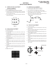
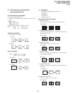
4-1. HV HOLD-DOWN ADJUSTMENT
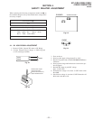
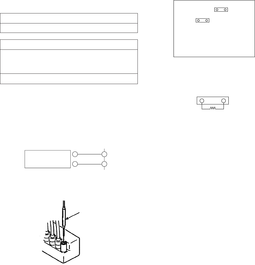
1. Remove CN810. Connect HV meter to HV Block.
2. Connect External Power Supply to CN810 2 pin
(+135V) and 1 pin (GND).
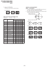
Part Replaced (])
E Board C515, C516, C554, D504, D507,
L506, Q502, R1, R514, R516,
R517, T502, T504 (FBT)
G Board IC6008
Part Replaced ([)
R1
3. Turn on the set.
4. Slowly up the supply voltage from 0V to 135V.
5. Receive dot picture and set PICTURE/BRIGHTNESS to
minimum.
6. Slowly up the voltage until hold-down circuit works (pic-
ture disappear).
7. Read the HV meter of peak HV voltage.
Spec: 34.5±0.75KV
8. If Hold-down voltage is less than 33.75KV then solder
R1=820K.
9. If hold-down voltage is over than 35.25KV then take-off
R514 and solder R1=9.1K.
+
–
2
CN810
Power
Supply
1
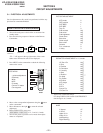
E BOARD
– CONDUCTOR SIDE –
CN810
CN505
CN505
R1
Fig. 4-1
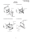
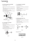
Fig. 4-2
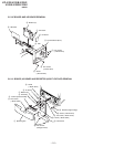
Fig. 4-3
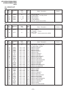
Fig. 4-4
Remove the cap off
from the unused
terminal and connect a
static voltmeter there.