2-4
ROUTING SWITCHER SYSTEM (E)
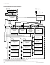
2-10. Setting the Input/Output Name (DVS-V3232B/V6464B, BKPF-R70 and HDS-V3232)
2-10. Setting the Input/Output Name
(DVS-V3232B/V6464B, BKPF-R70 and HDS-V3232)
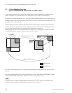
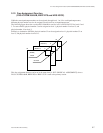
The following names can be used for the input/output connectors of the routing switcher.
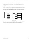
1. “Type+Number” name
2. ”Description“ name
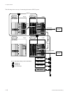
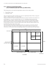
There are altogether three kinds of numbers that can be set as input/output numbers. These are “physical
number”, “connector number”, and “virtual number”.
The physical number and connector number are the number of connectors attached to the switcher. For a
DVS-V6464B, it is 1 to 64. For a DVS-V3232B, it is 1 to 32. The difference between the physical
number and connector number is that the connector number is used for each switcher frame, while the
physical number is used for one router system that is either single frame or multiple cascading frames.
Usually the physical number is used for the S-BUS control system, while the connector number is used
for the RS-422A (9-pin remote) control system.
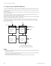
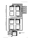
The virtual number is the numbers assigned when switchers are mapped on a virtual matrix with 512
inputs and 512 outputs. The numbers will not duplicate even if several switchers are mapped on the
virtual matrix. Unless otherwise noted, the input/output number in this manual means the virtual number.
Virtual Matrix
152 88 25 18
1
9
12
75
10
5
1
128
(64) (64)
(64)
(1) (1)
65 64
64
1
1
DVS-V6464B DVS-V6464B
DVS-V1616
(LEVEL-1)
DVS-V1616
(LEVEL-8)
INPUT
OUTPUT
Virtual number
Virtual number
Physical number
(Connector number)
Physical number
(Connector number)


