2-10
ROUTING SWITCHER SYSTEM (E)
*1 : Source means the input signal. Destination means the output signal.
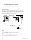
2-14. Tie Line Management (DVS-V3232B/V6464B, BKPF-R70 and HDS-V3232)
2-14. Tie Line Management
(DVS-V3232B/V6464B, BKPF-R70 and HDS-V3232)
If the primary station is a DVS-V3232B/V6464B, BKPF-R70 or HDS-V3232, by previously setting four
signal paths between routing switchers, unused signal paths can be selected automatically and protected
when input and output names are selected. This function is called tie line management. It is effective to
share the minimum number of converters (4:2:2:/4 fsc, 4 fsc/4:2:2, etc.).
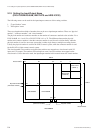
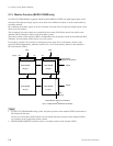
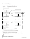
For example, if both a 4:2:2 video switcher and a 4 fsc video switcher have 32 sources and destinations,
the converters can be shared using the tie line function and all sources and destinations can be handled
with the minimum number of converters.
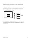
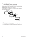
Setting Procedure of the Tie Line
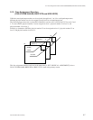
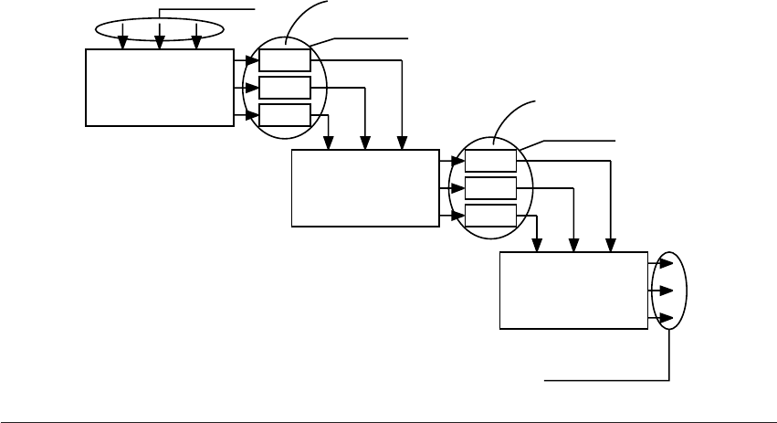
1. Set four input/output for each source/destination
*1
group.
2. Set the four cables connecting the switchers for each net groups such as “OUT * * * _ IN * * *”.
3. Set the path from the source group to the destination (the path consists of the selected group names)
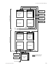
Routing Switcher
(4 : 2 : 2)
Routing Switcher
(4 fsc)
Source group
Net group
Net group
Destination group
Converter
Converter


