38 (EN)
TRIGGER
PLUG IN POWER
CONTROL S
IN OUT
REMOTE
RS-422A
INDEX
ABL LINK
IN OUT
VIDEO
S VIDEO
Y IN
C IN
INPUT A
R G B SYNC/HD VD
R-Y/P
R
Y B-Y/P
B
OUTOUT
IN
IN
IN OUT
MODE
REMOTE1
When making connections:
• Before connecting any cables, make sure that each
piece of equipment to be connected is turned off.
• Use cables appropriate for the equipment to be
connected.
• A loose connection may cause hum or noise.
• When disconnecting a cable, pull it out by the plug;
not the cable itself.
• Also refer to the instruction manual of the equipment
to be connected.
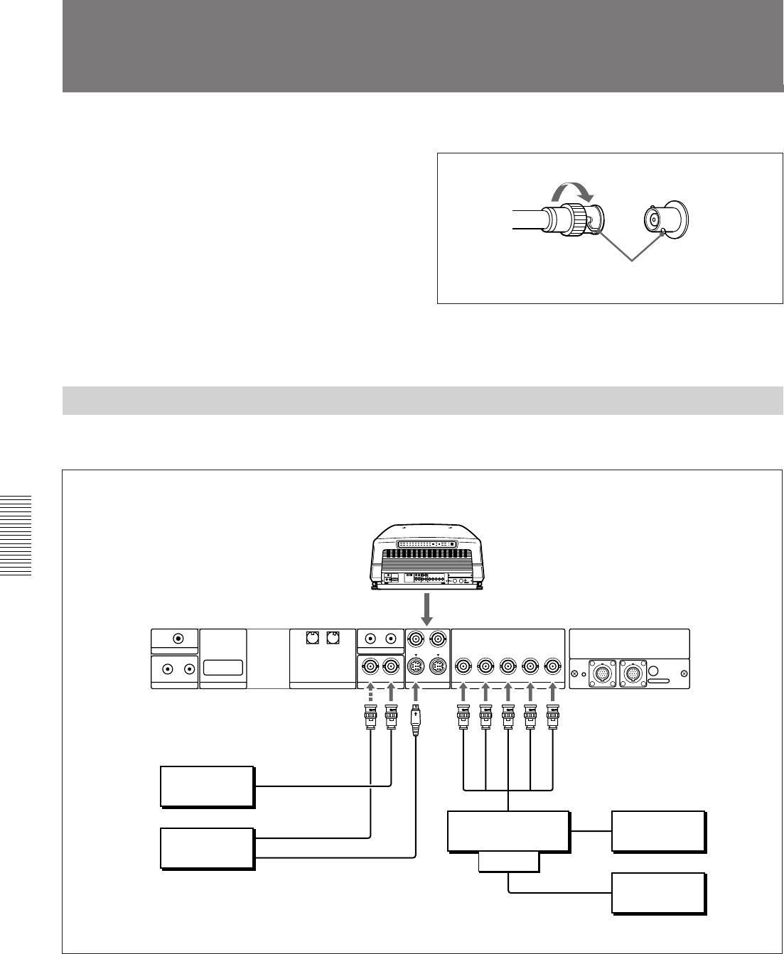
Connecting a BNC connector:
Connecting Directly to the Projector
Use the IFU-1271/1271M Signal Interface Unit.
2 Twist to the right.
1Align the pins with the pin holes and
push the plug into the socket.
Rear
IFU-1271/1271M
Computer
to S Video output
to video input
to RGB output
Color monitor
Color monitor
Setting up
• Set INPUT-A in the SET SETTING menu to RGB.
For details, see “The SET SETTING Menu” on page 31 (EN).
• Select VIDEO or S VIDEO by pressing the INPUT SELECT keys on the
remote control or by setting VIDEO in the INPUT SELECT menu.
For details, see “The INPUT SELECT Menu” on page 25 (EN).
Video equipment
IFB-12
to RGB Input
to RGB
input
to RGB output
to video output
Connection Examples
VIDEO IN
VIDEO OUT
S VIDEO IN
R
G
B
SYNC/HD
VD


