


SY-7VMA-B
Quick Start Guide
9
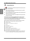
Hardware
Installation
¡°
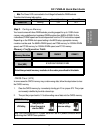
Note:
The Power LED is connected to the Voltage that feeds the DIMM sockets.
Therefore the following table applies:
Suspend to RAM Normal Operation Power Off
Power LED
Blinking ON OFF
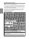
Step 3. Configure Memory
Your board comes with three DIMM sockets, providing support for up to 1.5GB of main
memory using unbuffered and registered DIMM modules from 8MB to 512MB. On this
motherboard, DRAM speed can be set independent from the CPU front side bus speed.
Depending on the DRAM clock speed setting in the BIOS setup, appropriate memory
modules must be used. For 66MHz DRAM speed, use PC66 memory; for 100MHz DRAM
speed, use PC100 memory; for 133MHz DRAM speed, use PC133 memory.
Memory Configuration Table
Number of
Memory Modules
DIMM 1 DIMM 2 DIMM 3
RAM Type SDRAM / VCM SDRAM
Memory Module
Size (MB)
8/16/32/64/128/256/512 MB
Note:Always install memory modules in the order prescribed in this table.
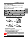
CMOS Clear (JP5)
In some cases the CMOS memory may contain wrong data, follow the steps below to clear
the CMOS memory.
1.
Clear the CMOS memory by momentarily shorting pin 2-3 on jumper JP5. This jumper
can be easily identified by its white colored cap.
2.
Then put the jumper back to 1-2 to allow writing new of data into the CMOS memory.
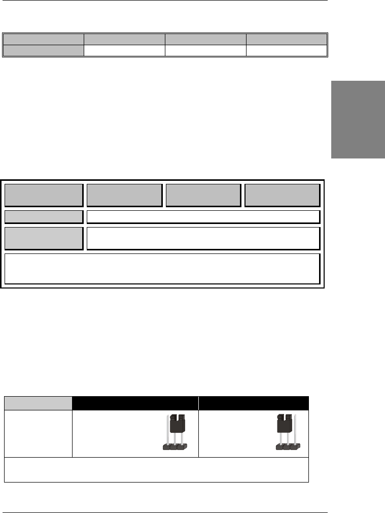
CMOS Clearing
Clear CMOS Data Retain CMOS Data
JP5 Setting
Short pin 2-3 for
at least 5 seconds to
clear the CMOS
Short pin 1-2 to
retain new settings
Note: You must unplug the ATX power cable from the ATX power connector when
performing the CMOS Clear operation.
123
12
3