


SpectraLink Corporation Installation, Configuration, and Administration
NetLink SVP Server (within IP environments)
PN: 72-0178-01-F.doc Page 15
Screw the other end of the two mounting plates (oblong screw holes) to the rack.
Repeat steps 1-3 for each additional SVP Server. The mounting plate is designed
to provide the correct minimum spacing between units. When mounting multiple
units, stack the units in the rack as closely as possible.
Mount the NetLink SVP Server to a wall
The NetLink SVP Server can be mounted either horizontally or vertically.
To mount the NetLink SVP Server to a wall:
1. Using a 1/8-inch drill bit, drill four pilot holes, on 1.84-inch by 12.1-inch centers
(approximately equivalent to 1-13/16” by 12-1/8”).
2. Insert the #8 3/4-inch screws in the pilot holes and tighten, leaving a 1/8-inch
to 1/4-inch-gap from the wall.
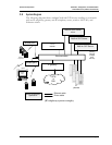
Connect NetLink SVP Server to LAN
Using a Cat. 5 cable, connect the NETWORK port on the NetLink SVP Server to the
connecting port on the Ethernet switch.
Connect Power
1. Connect the power plug from the AC adapter to the jack labeled PWR on the
NetLink SVP Server.
Use only the provided Class II AC Adapter with output 24VDC, 1A.
2. Plug the AC adapter into an 110VAC outlet to apply power to the NetLink SVP
Server.
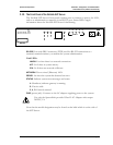
3. The system will cycle through diagnostic testing and the LEDs will blink for
about one minute. When the system is ready for use:
• The ERROR LED should be off.
• Status 1 should be blinking.