


LAN9118 Family Programmer Reference Guide
SMSC AN 12.12 43 Revision 1.0 (12-14-09)
APPLICATION NOTE
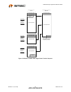
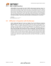
Figure 8.1 Oscilloscope/Logic Analyzer Display
GPIOs can also be used with a scope for instrumentation. Most scopes provide a way to measure the
time between events. In the trace above, the scope could be used to measure the time between the
rising and falling edges of GP_1, revealing the length of time it takes to read a packet out of the Rx
data FIFO with high accuracy. Measurements of the low time could be used to calculate the percentage
of bus usage. Almost any timing measurement imaginable can be measured using GPIOs and a scope.
GPIOs can also be used to create trigger points for the scope. If some kind of error is occurring in the
driver, it is useful to see what other events are occurring simultaneously. Pulsing the GPIO pin when
the error condition occurs provides a convenient sampling point for these events.
8.3 TxCLK and RxCLK
These signals can also be brought out on the GPIO pins to observe TX and RX characteristics. They
could be used in conjunction with an inexpensive frequency meter during a manufacture test to
measure the data bit rate on the wire. A frequency meter with accuracy of 50 ppm or better is
generally required to determine standards compliance.
8.4 Error Interrupts are Invaluable Tools
There are several interrupts available for detecting errors. Some of them can signal when the driver is
using the FIFOs incorrectly. They are Receiver Error (RXE), and Transmitter Error (TXE). If the driver
makes any mistakes with respect to data alignment, offsets, etc., it will trigger one of these interrupts.
When combined with a GPIO trigger pulse or a warning message, these interrupts can contribute
greatly to the robustness of the driver, because under normal operation these errors never occur. If
they do, then the driver likely has a bug which should be investigated.