


Small Footprint RMII 10/100 Ethernet Transceiver with HP Auto-MDIX Support
Datasheet
SMSC LAN8720/LAN8720i 15 Revision 1.0 (05-28-09)
DATASHEET
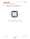
3.1 MAC Interface Signals
3.2 LED Signals
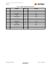
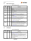
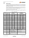
Table 3.2 RMII Signals 24-QFN
SIGNAL
NAME
24-QFN
PIN # TYPE DESCRIPTION
TXD0 17 I8 Transmit Data 0: The MAC transmits data to the PHY using this signal in
all modes.
TXD1 18 I8 Transmit Data 1: The MAC transmits data to the PHY using this signal in
all modes
TXEN 16 IPD Transmit Enable: Indicates that valid data is presented on the TXD[1:0]
signals, for transmission.
RXD0/
MODE0
8IOPUReceive Data 0: Bit 0 of the 4 data bits that are sent by the PHY in the
receive path.
PHY Operating Mode Bit 0: set the default MODE of the PHY.
See Section 5.3.9.2 for information on the MODE options.
RXD1/
MODE1
7IOPUReceive Data 1: Bit 1 of the 4 data bits that are sent by the PHY in the
receive path.
PHY Operating Mode Bit 1: set the default MODE of the PHY.
See Section 5.3.9.2 for information on the MODE options.
RXER/
PHYAD0
10 IOPD Receive Error: Asserted to indicate that an error was detected somewhere
in the frame presently being transferred from the PHY.
The RXER signal is optional in RMII Mode.
This signal is mux’d with PHYAD0
See Section 5.3.9.1 for information on the ADDRESS options.
CRS_DV/
MODE2
11 IOPU RMII Mode CRS_DV (Carrier Sense/Receive Data Valid) Asserted to
indicate when the receive medium is non-idle. When a 10BT packet is
received, CRS_DV is asserted, but RXD[1:0] is held low until the SFD byte
(10101011) is received. In 10BT, half-duplex mode, transmitted data is not
looped back onto the receive data pins, per the RMII standard.
PHY Operating Mode Bit 2: set the default MODE of the PHY.
See Section 5.3.9.2 for information on the MODE options.
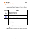
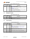
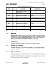
Table 3.3 LED Signals 24-QFN
SIGNAL
NAME
24-QFN
PIN # TYPE DESCRIPTION
LED1/
REGOFF
3IOPDLED1 – Link activity LED Indication.
See Section 5.3.7 for a description of LED modes.
Regulator Off: This pin may be used to configure the internal 1.2V regulator
off. As described in Section 4.11, this pin is sampled during the power-on
sequence to determine if the internal regulator should turn on. When the
regulator is disabled, external 1.2V must be supplied to VDDCR.
When LED1/REGOFF is pulled high to VDD2A with an external resistor, the
internal regulator is disabled.
When LED1/REGOFF is floating or pulled low, the internal regulator is
enabled (default).