


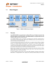

Hi-Speed USB 2.0 to 10/100 Ethernet Controller
Datasheet
Revision 1.7 (10-02-08) 12 SMSC LAN9500/LAN9500i
DATASHEET
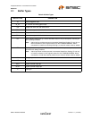
Note 2.1 Configuration strap values are latched on power-on reset and system reset. Configuration
straps are identified by an underlined symbol name. Signals that function as configuration
straps must be augmented with an external resistor when connected to a load.
1
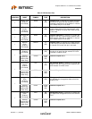
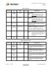
Transmit Data
1
(External
PHY Mode)
TXD1 O8
(PD)
Transmit Data 1: In external PHY mode, this pin
functions as the transmit data 1 output to the
external PHY.
General
Purpose I/O 5
(Internal PHY
Mode Only)
GPIO5 IS/O8/
OD8
(PU)
General Purpose I/O 5
Remote
Wakeup
Configuration
Strap
RMT_WKP
IS
(PD)
Remote Wakeup Configuration Strap: This
strap configures the default descriptor values to
support remote wakeup.
0 = Remote wakeup is not supported.
1 = Remote wakeup is supported.
See Note 2.1 for more information on
configuration straps.
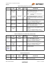
1
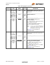
Transmit Data
0
(External
PHY Mode)
TXD0 O8
(PD)
Transmit Data 0: In external PHY mode, this pin
functions as the transmit data 0 output to the
external PHY.
General
Purpose I/O 4
(Internal PHY
Mode Only)
GPIO4 IS/O8/
OD8
(PU)
General Purpose I/O 4
EEPROM
Disable
Configuration
Strap
EEP_DISABLE IS
(PD)
EEPROM Disable Configuration Strap: This
strap disables the autoloading of the EEPROM
contents. The assertion of this strap does not
prevent register access to the EEPROM.
0 = EEPROM is recognized if present.
1 = EEPROM is not recognized even if it is
present.
See Note 2.1 for more information on
configuration straps.
1
Transmit
Clock
(External
PHY Mode)
TXCLK IS
(PU)
Transmit Clock: In external PHY mode, this pin
is the transmitter clock input from the external
PHY. In internal PHY mode, this pin is not used.
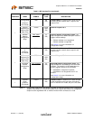
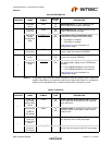
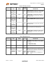
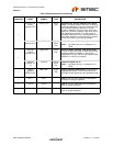
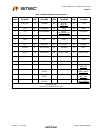
Table 2.1 MII Interface Pins (continued)
NUM PINS NAME SYMBOL
BUFFER
TYPE DESCRIPTION