


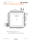

Hi-Speed USB 2.0 to 10/100 Ethernet Controller
Datasheet
SMSC LAN9500/LAN9500i 17 Revision 1.7 (10-02-08)
DATASHEET
1
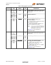
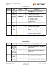
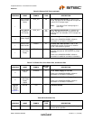
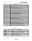
PHY Interrupt
(Internal PHY
Mode)
nPHY_INT O8 PHY Interrupt (Active-Low): In internal PHY
mode, this signal can be configured to output the
internal PHY interrupt signal.
Note: The internal PHY interrupt signal is
active-high.
PHY Interrupt
(External
PHY Mode)
nPHY_INT IS
(PU)
PHY Interrupt (Active-Low): In external PHY
mode, the signal on this pin is input from the
external PHY and indicates a PHY interrupt has
occurred.
4
+3.3V Analog
Power Supply
VDD33A P +3.3V Analog Power Supply
Refer to the LAN9500/LAN9500i reference
schematic for connection information.
1
External PHY
Bias Resistor
EXRES AI External PHY Bias Resistor: Used for the
internal bias circuits. Connect to an external
12.4K 1.0% resistor to ground.
1
Ethernet PLL
+1.8V Power
Supply
VDD18PLL P Ethernet PLL +1.8V Power Supply: This pin
must be connected to VDD18CORE for proper
operation.
Refer to the LAN9500/LAN9500i reference
schematic for additional connection information.
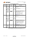
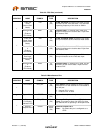
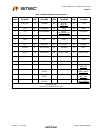
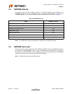
Table 2.7 I/O Power Pins, Core Power Pins, and Ground Pad
NUM PINS NAME SYMBOL
BUFFER
TYPE DESCRIPTION
5
+3.3V I/O
Power
VDD33IO P +3.3V Power Supply for I/O Pins
Refer to the LAN9500/LAN9500i reference
schematic for connection information.
2
Digital Core
+1.8V Power
Supply
Output
VDD18CORE P Digital Core +1.8V Power Supply Output
Refer to the LAN9500/LAN9500i reference
schematic for connection information.
Exposed
pad on
package
bottom
(Figure 2.1)
Ground VSS P Common Ground
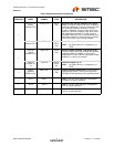
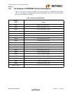
Table 2.8 No-Connect Pins
NUM PINS NAME SYMBOL
BUFFER
TYPE DESCRIPTION
1
No Connect NC - No Connect: These pins must be left floating for
normal device operation
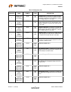
Table 2.6 Ethernet PHY Pins (continued)
NUM PINS NAME SYMBOL
BUFFER
TYPE DESCRIPTION