


USB 2.0 Hi-Speed Hub Controller
Datasheet
SMSC USB251x 29 Revision 1.0 (3-11-09)
DATASHEET
Chapter 6 LED Usage Description
6.1 LED Functionality
USB2513 and USB2514 (48-pin QFN only) and USB2517/17i SMSC hubs support two different
(mutually exclusive) LED modes. The ‘x’ represents the number of downstream ports. The USB mode
provides up to 14 LED’s that conform to the USB 2.0 specification functional requirements for Green
and Amber LED’s. The LED mode “speed indicator” provides the downstream device connection
speed.
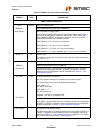
6.1.1 USB Mode 14-Wire
The LED_A_N[x:1] pins are used to provide Green LED support as defined in the USB 2.0
specification. The LED_B_N[x:1] pins are used to provide Amber LED support as defined in the USB
2.0 specification. The USB specification defines the LED’s as port status indicators for the downstream
ports. Please note that no indication of port speed is possible in this mode. The pins are utilized as
follows:
LED_A_N[x:1] = Port [x:1] green LED
LED_B_N[x:1] = Port [x:1] amber LED
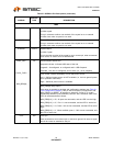
6.1.2 LED Mode Speed Indication
The LED_A[x:1]_N pins are used to provide connection status as well as port speed by using dual
color LED's. This scheme requires that the LED's be in the same package, and that a third color is
produced so that the user perceives both LED's as being driven "simultaneously".
The LED_A[x:1] pins used in this mode are connected to x number of dual color LED’s (each LED pair
in a single package). These pins indicate the USB speed of each attached downstream device.
Each dual color LED provides two separate colors (commonly Green and Red). If each of these
separate colors are pulsed on and off at a rapid rate, a user will see a third color (in this example,
Orange). Using this method, 4 different "color" states are possible (Green, Red, Orange, and Off).
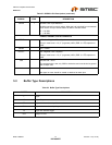
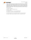
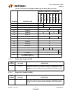
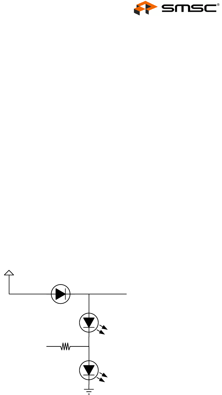
Figure 6.1 Dual Color LED Implementation Example
Hub LED pin
D1A (Green LED)
D1B (Red LED)
3.3 V
General
Purpose
Diode
Current Limiting
Resistor
Connection to
other Dual Color
Diodes