


USB 2.0 High-Speed 4-Port Hub Controller
Datasheet
Revision 1.98 (11-19-07) 24 SMSC USB2514
DATASHEET
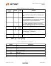
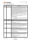
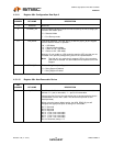
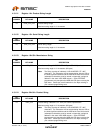
4.3.1.9 Register 08h: Configuration Data Byte 3
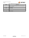
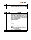
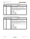
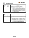
4.3.1.10 Register 09h: Non-Removable Device
BIT
NUMBER BIT NAME DESCRIPTION
7:4 Reserved Reserved
3 PRTMAP_EN Port Re-mapping enable: Selects the method used by the hub to assign port
numbers and disable ports.
‘0’ = Standard Mode
‘1’ = Port Re-map mode
2:1 LED_MODE LED Mode Selection: The LED_A[4:1]_N and LED_B[4:1]_N pins support
several different modes of operation.
‘00’ = USB Mode
‘01’ = Speed Indication Mode
‘10’ = Same as ‘00’, USB Mode
‘11’ = Same as ‘00’, USB Mode
Warning: Do not enable an LED mode that requires LED pins that are not
available in the specific package being used in the implementation!
Note: The Hub will only report that it supports LED's to the host when
USB mode is selected. All other modes will be reported as No LED
Support.
0 STRING_EN Enables String Descriptor Support
‘0’ = String Support Disabled
‘1’ = String Support Enabled
BIT
NUMBER BIT NAME DESCRIPTION
7:0 NR_DEVICE Non-Removable Device: Indicates which port(s) include non-removable
devices. ‘0’ = port is removable, ‘1’ = port is non-removable.
Informs the Host if one of the active ports has a permanent device that is
undetachable from the Hub. (Note: The device must provide its own
descriptor data.)
When using the internal default option, the NON_REM[1:0] pins will
designate the appropriate ports as being non- removable.
Bit 7= Reserved
Bit 6= Reserved
Bit 5= Reserved
Bit 4= 1; Port 4 non-removable
Bit 3= 1; Port 3 non-removable
Bit 2= 1; Port 2 non-removable
Bit 1= 1; Port 1 non removable
Bit 0 is Reserved, always = ‘0’