


USB 2.0 High-Speed 4-Port Hub Controller
Datasheet
SMSC USB2514 37 Revision 1.98 (11-19-07)
DATASHEET
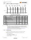
4.4.7 Bus Reset Sequence
The SMBus Slave Interface resets and returns to the idle state upon a START field followed
immediately by a STOP field.
4.4.8 SMBus Alert Response Address
The SMBALERT# signal is not supported by the Hub.
4.4.8.1 Undefined Registers
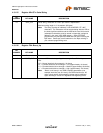
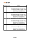
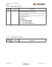
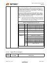
The registers shown in Table 4.2 are the defined registers in the Hub. Reads to undefined registers
return 00h. Writes to undefined registers have no effect and do not return an error.
4.4.8.2 Reserved Registers
Unless otherwise instructed, only a ‘0’ may be written to all reserved registers or bits.
4.5 Default Configuration Option:
The SMSC Hub can be configured via its internal default configuration. (please see Section 4.3.1,
"Internal Register Set (Common to EEPROM and SMBus)" for specific details on how to enable default
configuration.)
Please refer to Table 4.2 for the internal default values that are loaded when this option is selected.
4.6 Default Strapping Options:
The USB2514 can be configured via a combination of internal default values and pin strap options.
Please see Table 3.1 and Table 3.2 for specific details on how to enable the default/pin-strap
configuration option.
The strapping option pins only cover a limited sub-set of the configuration options. The internal default
values will be used for the bits & registers that are not controlled by a strapping option pin. Please
refer to Table 4.2 for the internal default values that are loaded when this option is selected.
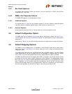
The Amber and Green LED pins are sampled after RESET_N negation, and the logic values are used
to configure the hub if the internal default configuration mode is selected. The implementation shown
below (see Figure 4.3) shows a recommended passive scheme. When a pin is configured with a “Strap
High” configuration, the LED functions with active low signalling, and the PAD will “sink” the current
from the external supply. When a pin is configured with a “Strap Low” configuration, the LED functions
with active high signalling, and the PAD will “source” the current to the external LED.