


Small Footprint Hi-Speed USB 2.0 Device PHY with UTMI Interface
Datasheet
Revision 1.5 (11-02-07) 16 SMSC USB3290
DATASHEET
Note 6.5 V
DD3.3
= 3.0 to 3.6V; V
SS
= 0V; T
A
= -40
o
C to 85
o
C; unless otherwise specified.
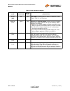
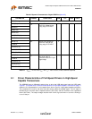
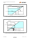
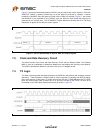
6.1 Driver Characteristics of Full-Speed Drivers in High-Speed
Capable Transceivers
The USB3290 uses a differential output driver to drive the USB data signal onto the USB cable.
Figure 6.1 Full-Speed Driver VOH/IOH Characteristics for High-speed Capable Transceiveron page 17
shows the V/I characteristics for a full-speed driver which is part of a high-speed capable transceiver.
The normalized V/I curve for the driver must fall entirely inside the shaded region. The V/I region is
bounded by the minimum driver impedance above (40.5 Ohm) and the maximum driver impedance
below (49.5 Ohm). The output voltage must be within 10mV of ground when no current is flowing in
or out of the pin.
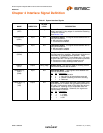
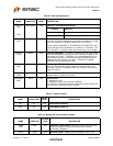
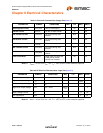
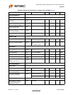
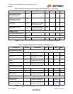
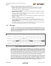
Table 6.5 Dynamic Characteristics: Digital UTMI Pins (Note 6.5)
PARAMETER SYMBOL CONDITIONS MIN TYP MAX UNITS
UTMI Timing
DATA[7:0] T
PD
Output Delay. Measured
from PHY output to the
rising edge of CLKOUT
25ns
RXVALID
RXACTIVE
RXERROR
LINESTATE[1:0]
TXREADY
DATA[7:0] T
SU
Setup Time. Measured
from PHY input to the
rising edge of CLKOUT.
5ns
TXVALID
OPMODE[1:0]
XCVRSELECT
TERMSELECT
DATA[7:0] T
H
Hold time. Measured from
the rising egde of
CLKOUT to the PHY input
signal edge.
0ns
TXVALID
OPMODE[1:0]
XCVRSELECT
TERMSELECT