


Small Footprint Hi-Speed USB 2.0 Device PHY with UTMI Interface
Datasheet
Revision 1.5 (11-02-07) 30 SMSC USB3290
DATASHEET
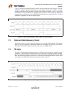
8.4 SE0 Handling
For FS operation, IDLE is a J state on the bus. SE0 is used as part of the EOP or to indicate reset.
When asserted in an EOP, SE0 is never asserted for more than 2 bit times. The assertion of SE0 for
more than 2.5us is interpreted as a reset by the device operating in FS mode.
For HS operation, IDLE is a SE0 state on the bus. SE0 is also used to reset a HS device. A HS
device cannot use the 2.5us assertion of SE0 (as defined for FS operation) to indicate reset since the
bus is often in this state between packets. If no bus activity (IDLE) is detected for more than 3ms, a
HS device must determine whether the downstream facing port is signaling a suspend or a reset. The
following section details how this determination is made. If a reset is signaled, the HS device will then
initiate the HS Detection Handshake protocol.
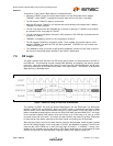
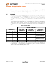
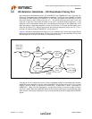
8.5 Reset Detection
If a device in HS mode detects bus inactivity for more than 3ms (T1), it reverts to FS mode. This
enables the FS pull-up on the DP line in an attempt to assert a continuous FS J state on the bus. The
SIE must then check LINESTATE for the SE0 condition. If SE0 is asserted at time T2, then the
upstream port is forcing the reset state to the device (i.e., a Driven SE0). The device will then initiate
the HS detection handshake protocol.
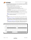
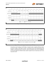
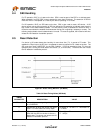
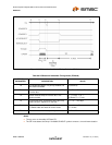
Figure 8.1 Reset Timing Behavior (HS Mode)
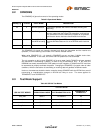
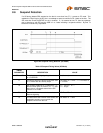
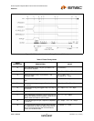
Table 8.4 Reset Timing Values (HS Mode)
TIMING
PARAMETER DESCRIPTION VALUE
HS Reset T0 Bus activity ceases, signaling either a reset
or a SUSPEND.
0 (reference)
T1 Earliest time at which the device may place
itself in FS mode after bus activity stops.
HS Reset T0 + 3. 0ms < T1 < HS Reset T0
+ 3.125ms
T2 SIE samples LINESTATE. If LINESTATE =
SE0, then the SE0 on the bus is due to a
Reset state. The device now enters the HS
Detection Handshake protocol.
T1 + 100µs < T2 <
T1 + 875µs