


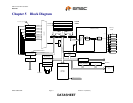
USB 2.0 Flash Drive Controller
Datasheet
SMSC USB97C242 Page 15 Revision 1.4 (05-03-07)
DATASHEET
Note: nMCE is normally asserted except when the 8051 is in standby mode.
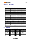
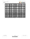
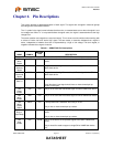
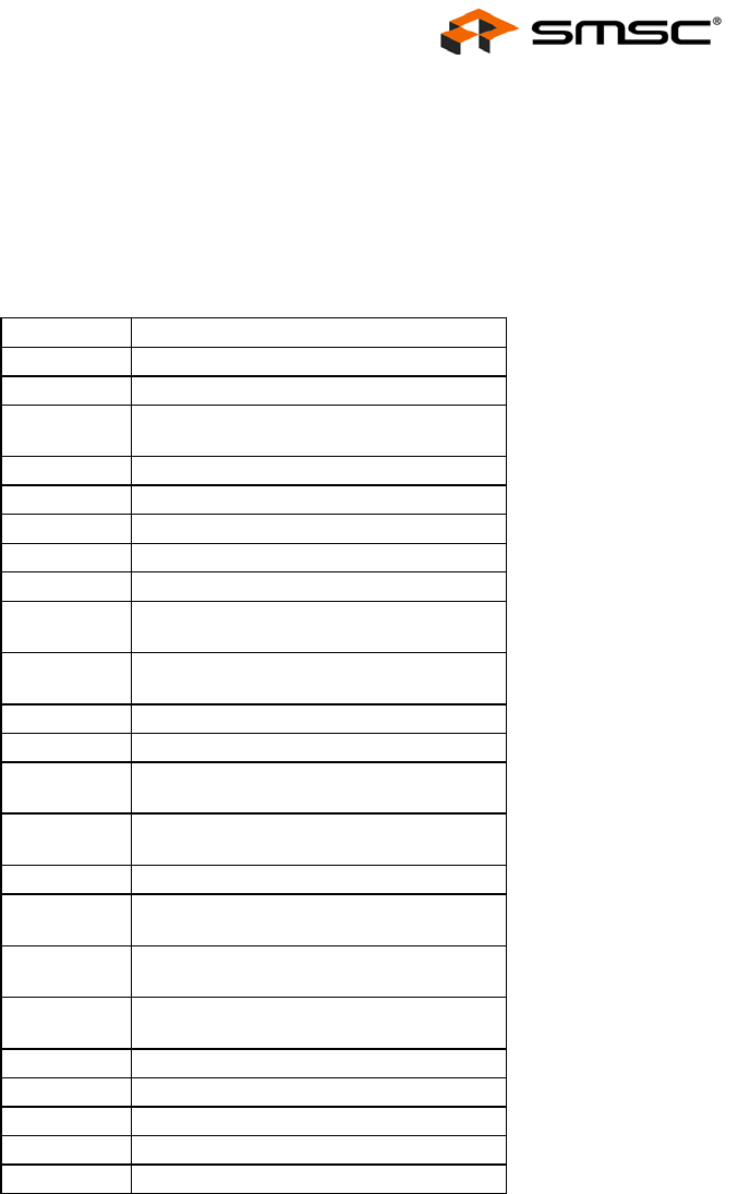
6.1 Buffer Type Descriptions
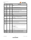
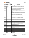
Table 6.2 - USB97C242 Buffer Type Descriptions
BUFFER DESCRIPTION
I Input
IPU Input with internal weak pull-up resistor.
IPD Input with internal weak pull-down
resistor.
IS Input with Schmitt trigger
I/O4 Input/Output with 4mA drive
I/OD4 Input/Open drain output … 4mA sink
I/O8 Input/Output with 8mA drive
I/OD8 Input/Open drain output … 8mA sink
I/OPD8 Input/Output with 8mA drive and
controlled weak pull down.
I/OPU8 Input/Output with 8mA drive and
controlled weak pull up.
O4 Output with 4mA drive
O8 Output with 8mA drive
OPD8 Output with 8mA drive and controlled
weak pull down.
OPU8 Output with 8mA drive and controlled
weak pull up.
I/O12 Output with 12mA drive
I/OPU12 Input/Output with 12mA drive and
controlled weak pull up on input.
OPU12 Output with 12mA drive and controlled
weak pull up.
OPD12 Output with 12mA drive and controlled
weak pull down.
O12 Output with 12mA drive
OD12 Open drain….12mA sink
ICLKx XTAL clock input
OCLKx XTAL clock output
I/O-U Defined in USB specification