


TABLE OF CONTENTS
1. OUTLINE .............................................................................................. 1
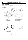
2. UNPACKING AND INSTALLATION ................................................ 2
2-1. Unpacking .................................................................................... 2
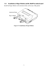
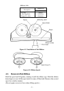
2-2. Installation of Paper Holders and Re-Roll
Prevention Guard ......................................................................... 3
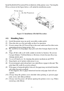
2-3. Handling Notes............................................................................. 4
3. PART IDENTIFICATION AND NOMENCLATURE ........................ 5
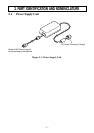
3-1. Power Supply Unit .......................................................................5
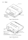
3-2. Printer ........................................................................................... 6
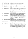
3-3. Part Functional Description.......................................................... 7
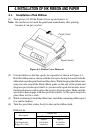
4. INSTALLATION OF INK RIBBON AND PAPER............................. 8
4-1. Installation of Ink Ribbon ............................................................8
4-2. Removal of Ink Ribbon ................................................................ 9
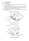
4-3. Paper Insertion ........................................................................... 10
4-3-1. For Roll Paper .................................................................10
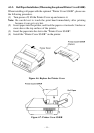
4-3-2. Roll Paper Installation
(When using the optional Printer Cover 8340R) .............11
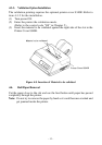
4-3-3. Validation Option Installation ......................................... 12
4-4. Roll Paper Removal ...................................................................12
5. CONTROL CODES ............................................................................ 13
6. GENERAL SPECIFICATIONS ..........................................................20
7. INTERFACE FOR MODEL DP8340RM
(MODULAR JACK CONNECTOR) .................................................. 24
7-1. Interface Specifications .............................................................. 24
7-2. Interface Circuit ......................................................................... 24
7-3. Setting of the DIP Switches .......................................................25
7-3-1. DIP-SW 1 ........................................................................ 25
7-3-2. DIP-SW2 ......................................................................... 25
7-4. Connectors and Signals .............................................................. 26
7-5. Interface Connections................................................................. 27
7-6. Peripheral Unit Drive Circuit ..................................................... 28
7-6-1. Cable Connection ............................................................28
7-6-2. Peripheral Drive Circuit .................................................. 29
7-6-3. Control Codes.................................................................. 29