


– 34 –
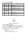
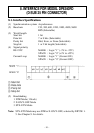
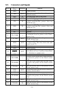
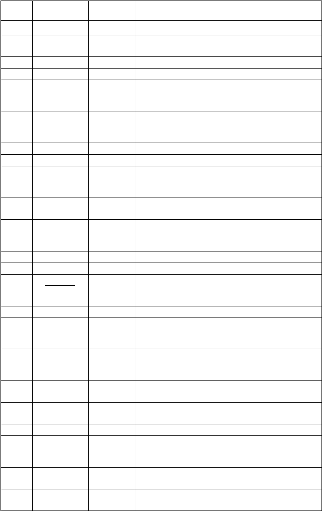
Pin No.
Signal
Direction Function
Name
1 GND — Frame Ground
2 TXD OUT
This pin carries data from the printer.
(Return channel)
3 RXD IN This pin carries data to the printer.
4 RTS OUT This is SPACE when the printer power is ON.
5 CTS IN
This pin is SPACE when the computer is
ready to send data.The printer does not
check this pin.
6 DSR IN
This pin is SPACE when the computer is
ready to send data.The printer does not
check this pin.
7 GND — Signal ground.
8 N/C Unused.
9 TTY TXDR —
This pin is the return path for data
transmitted from the printer on the 20mA
current loop.
10 TTY TXD OUT
This pin carries data from the printer on the
20mA current loop.
11 RCH OUT
This pin is SPACE when the printer is ready
to receive data. This line carries the same
signal as pin 20.
12 N/C Unused.
13 GND — Signal ground.
14 FAULT OUT
This is MARK when the printer is abnor-
mal. (Refer to Error Condition Alarm Mode
*1.) Or there is a paper error.
15 ~ 16 N/C Unused.
17 TTY TXDR —
This pin is the return path for data transmit-
ted from the printer on the 20mA current
loop.
18 TTY RXDR —
This pin is the return path for data trans-
mitted to the printer on the 20mA current
loop.
19 TTY RXD IN
This pin carries data to the printer on the
20mA current loop.
20 DTR OUT
This printer turns this pin SPACE when it is
ready to receive data.
21 ~ 22 N/C Unused.
23 TTY RXDR —
This pin is the return path for data trans-
mitted to the printer on the 20mA current
loop.
24 TTY TXD OUT
This pin carries data from the printer on the
20mA current loop.
25 TTY RXD IN
This pin carries data to the printer on the
20mA current loop.
8-5. Connectors and Signals