


131
APPENDIX
Appendix D: Interface
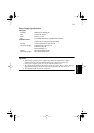
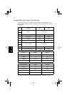
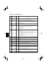
D-1. Serial Interface
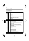
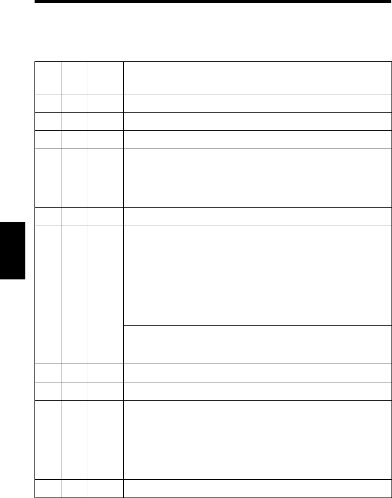
Pins and Signal Names
Pin
No.
Signal
Name
Direction Function
1FG — Frame ground
2 TXD OUT Transmission data
3 RXD IN Receive data
4 RTS OUT
STAR Mode
When Memory Switch 4-D = 0: Same as DTR signal
When Memory Switch 4-D = 1: Always SPACE
ESC/POS Mode
Same as DTR signal
5 N.C. Not connected
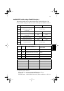
6 DSR IN
• DIP Switch 9 = OFF
STAR Mode
Status of this signal is not checked.
ESC/POS Mode
In DTR/DSR communication mode when Memory Switch4-5 = 0, indicates
whether data receive from host is enabled or disabled.
Space: Receive enabled
Mark: Receive disabled
This signal is not checked in the X-ON/X-OFF communication mode.
• DIP Switch 9 = ON
This signal used for external reset. Printer is reset whenever signal is in mark
state with pulse width of 1mS or more.
7 SG Signal ground
8 -19 N.C. Not connected
20 DTR OUT Indicates whether data receive from host is enabled or disabled.
DTR/DSR Communication Mode
Space when receive is enabled.
X-On/X-Off Communication Mode
Always space, except during following conditions:
• Period between reset and communication enabled
• During self-test printing and dot alignment adjustment
21 - 24 N.C. Not connected