


– 24 –
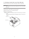
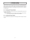
E
C
R3 R4
R3
=
3.5kΩ
R4
=
300Ω
B
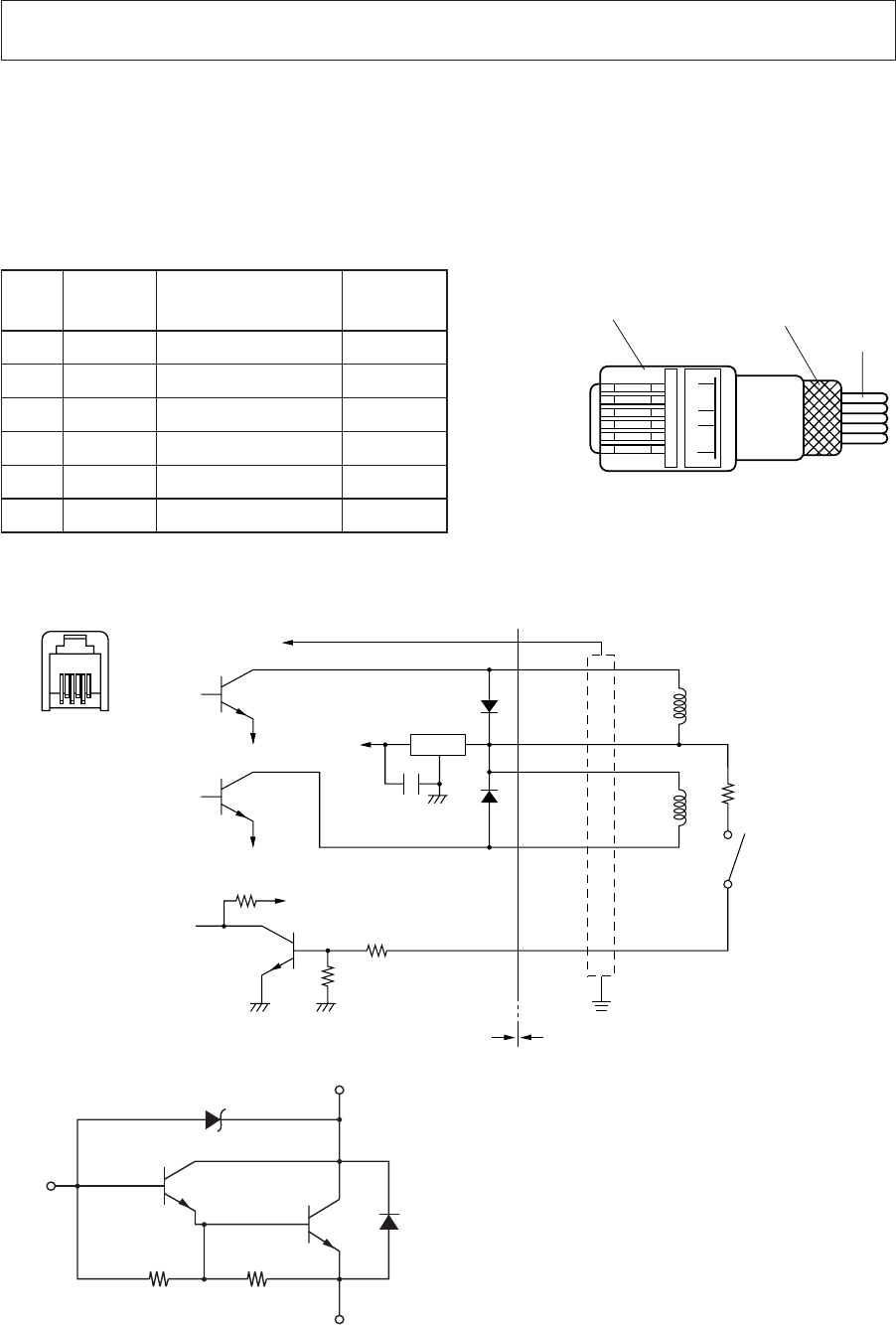
Modular plug
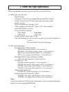
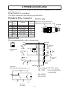
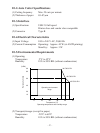
Peripheral Drive Connector
Pin No.
Signal
Function
I/O
name direction
1 FG Frame ground —
2 DRD1 Drive signal 1 OUT
3 +24V Drive power OUT
4 +24V Drive power OUT
5 DRD2 Drive signal 2 OUT
6 DRSNS Sense signal IN
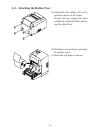
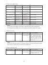
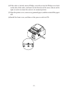
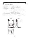
9. Periheral Unit Drive Circuit
Peripheral unit drive circuit connector only connects to peripheral units such as
cash drawers, etc.
Do not connect it to a telephone.
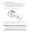
Use cables which meet the following specifications.
16
Modular plug: MOLEX 90075-0007,
AMP641337, or BURNDY B-66-4
Wire lead
Shield
Drive circuit
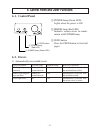
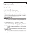
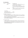
The recommended drive unit is shown below.
61
6-P Modular jack
connector
7824
F.G
TR1
M-GND
TR2
M-GND
TR3
+5V
+24V
R1
R2
6
5
4
3
2
1
L1
L2
R3
4.7kΩ
1/4W
Frame
ground
Printer side User side
D1
D2
Peripheral
unit 1
With shield
Peripheral
unit 2
Compulsion
switch
Drive Output:24V, Max. 1.0A
TR1, TR2: Transistor 2SD1866
or equivalent
R1=10 kΩ
R2=33 kΩ
Reference
2SD 1866 Circuit Configuration